
User Manual Manual

Applications/Wiring 9-2
Publication 825-UM001B-EN-P January 2001
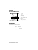
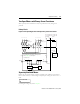
Control Circuit
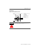
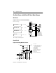
Figure 9.2 Control by Momentary Contact
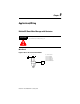
ATTENTION
!
The mounting/wiring directions and the specifications of the
contactor being used must be considered.
AL
A1
95 97
96
98 A2
A1
A2
H2
(L2/F8)
N
K1
H1
K1
H3
825-M
13
14
F7
L1
S0
S1
MR
F1
U
s
K1 Contactor
F1 Bulletin 825 Smart Motor Manager
S1 On push button
S0 Off push button
U
s
Control voltage
H1 Indicator “Contactor closed“
H2 Indicator “825-M tripped“
MR Main relay
AL Alarm relay
H3 Indicator “Alarm/Warning“