
User Manual Manual

Commissioning and Operation 6-4
Publication 825-UM001B-EN-P January 2001
Locked Rotor or Starting Current
• Set the locked-rotor or starting current as the multiple of rated current I
A
: I
e
according to specifications given by the manufacturer.
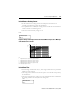
• If no specifications are available, the starting current can either be measured with the
current converter or read from Figure 6.1
• The current converter factory setting is 6 x I
e
.
LCD:
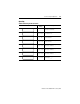
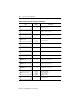
Figure 6.1 Range of Starting Currents of Standard Motors Expressed as Multiple
of the Rated Service Current
P
N
1 Approximate value for 2-pole motors, speed 3 000 rpm
2 Approximate value for 4-pole motors, speed 1 500 rpm
3 Approximate value for 6-pole motors, speed 1 000 rpm
4 Approximate value for 8-pole motors, speed 750 rpm
P
N
Rated output power in service
Locked Rotor Time
• Normal setting of locked rotor time (i.e., when using standard motors or permissible
locked rotor time is known)
• The setting of the locked rotor time must be equal to or less than the value quoted by
the manufacturer.
• The current converter factory setting is 10 s. If no application details are available and
the starting conditions are normal, leave the setting at 10 s.
LCD:
LOCKED ROT CURR
6.00 x Ie
2
0.4
1
2
0.2
4
10
20
40
100
200
3
4
6
8
10
1
123 4
I
e
I
A
kW
LOCKED ROT TIME
10 sec