
User Manual Manual

Commissioning and Operation 6-2
Publication 825-UM001B-EN-P January 2001
Checking the Wiring
• Primary current transformer, core balance current transformers
• Converter module
• Basic Unit
• Link between basic unit and converter module
• Inputs, outputs
• Supply
• Communication
• Contacts 95…98 are marked according to “electrically held”/“non-fail-safe”
connection required.
Checking the Installation with the Control Voltage Applied
Switching on the Control Voltage
After applying control voltage, the current converter is ready for operation in
approximately 3 s.
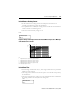
• LCD shows “ACTUAL VALUE”
• Main relay; contact 95/96 is closed
Checking the Set Parameters
Methods
• With the current converter in Set Values mode
Access the parameters (or print them out) and compare them with the set values in the list of
settings. The main settings are:
• Rated or service current
• Locked-rotor or starting current
• Permissible locked-rotor time
These three settings must be made individually for each motor. Refer to page5-4, Operational
Parameters, for procedure.