
User Manual Manual

4-9 Assembly and Installation
Publication 825-UM001B-EN-P January 2001
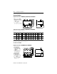
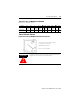
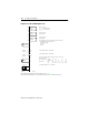
Figure 4.12 Cat. No. 825-MST Option Card
➊ For information regarding methods of actuation, refer to Chapter 9.
➋ Method of installation: up to 100 m (328 ft) twisted, more than 100 m additional unscreened
23
24
Aux
Relay #1
33
34
Aux
Relay #2
43
44
Aux
Relay #3
4...20 mA
(0...300 W)
I +
I -
A
Y31
Control
Input #1
Y32
Y41
Control
Input #2
Y42
T1
T2
PTC
L1 L2 L3
k
l
Auxiliary relay #1
IEC 400V AC/125V DC
UL/CSA 240V AC/125V DC
Auxiliary relay #2
50V AC/30V DC
Auxiliary relay #3
50V AC/30V DC
Analog output indicates the thermal utilization of the motor, the
motor temperature, or the motor current
Indicating instrument
PLC input
Recorder
Control input #1: 24V DC or 24V AC ➊
Control input #2: 24V DC or 24V AC ➊
Thermistor overtemperature protection max. 6 PTC wired in series
Measuring lead ➋
Min. cross-section [mm
2
] 0.5 0.75 1 1.5 2.5
[AWG No.] 20 18 17 16 14
Max. length [m] 200 300 400 600 1 000
[ft] 656 984 1 312 1 968 3 280
Core balance transformer 5…500 mA at k-l
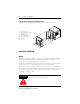
External Internal