
User Manual User Manual


Publication 825-UM002A-EN-P - December 2000
Installation 2-3
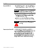
➇ ➈
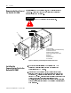
DeviceNet Connection
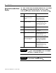
The Communication Card receives power and communicates through the
DeviceNet Connector (Se eFigure 1.1 and Figure 2.1 for the location of this
connector). DeviceNet cable wires connect to the plug in the connector
terminal block as shown in the following table.
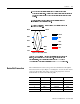
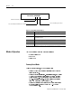
Figure 2.2 DeviceNet Label
Black
Blue
White
Red
Bare
Blue
Blue
Red
Red
Black
Black
Bare
White
White
Terminal Signal Function Color
1 V- Common Black
2 CAN_L Signal Low Blue
3 SHIELD Shield Uninsulated
4 CAN_H Signal High White
5 V+ Power Supply Red