Bulletin 825 Elektronisches Steuer- und Schutzsystem Electronic Control and Protection System Système électronique de commande et de protection Sistema elettronico di comando e protezione Sistema electrónico de mando y de protección Montageanleitung Installation Instructions Instructions de montage Istruzioni per il montaggio Instrucciones de montaje
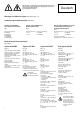
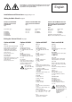
Alle Montage-, Inbetriebnahme- und Wartungsarbeiten müssen durch Fachpersonal, unter Berücksichtigung der örtlichen Vorschriften, ausgeführt werden. Systemhandbuch beachten. Deutsch Montage und Abmessungen siehe Seite 9, Fig. 6 / 7 / 8 Verdrahtung Hauptstromkreis siehe Seite 8 825-M* und 825-MCM* ohne Hauptstromwandler 825-M* und 825-MCM* mit Hauptstromwandler Fig. 1 Fig.
All installations, commissioning and maintenance must be carried out by qualified personnel, taking local regulations into account. Pay attention to the System Manual. English Installations and Dimensions see page 9, Fig. 6 / 7 / 8 Wiring the Main Circuit see page 8 825-M* and 825-MCM* without main current transformer 825-M* and 825-MCM* with main current transformer Fig. 2 Fig. 1 825-M* and 825-MCM* with twophase main current transformer and summation current transformer Fig.
Tous les traveaux de montage, de mise en service et de maintenance ne doivent être exécutés que par du personnel spécialisé en respectant les prescriptions locales. Consulter le manuel système. Français Montage et dimensions voir page 9, Fig. 6 / 7 / 8 Câblage du circuit principal voir page 8 Modèles 825-M* et 825-MCM* sans convertisseur de courant principal Modèles 825-M* et 825-MCM* avec convertisseur de courant principal Fig. 1 Fig.
Tutti i lavori di montaggio, messa in funzione e manutenzione devono essere eseguiti da personale specializzato, conformemente alle norme vigenti localmente. Attenersi al manuale del sistema. Italiano Montaggio e dimensioni vedere pagina 9, fig. 6 / 7 / 8 Cablaggio e dimensioni vedere pagina 8 825-M* e 825-MCM* senza transformatore di corrente principale 825-M* e 825-MCM* con trasformatore di corrente principale Fig. 1 Fig.
Todos los trabajos de montaje, de puesta en servicio y de mantenimiento deberán ser efectuados por personal especializado, considerando las prescripciones locales. Observar el manual de sistema. Español Montaje y dimensiones véase pág. 9, Fig. 6 / 7 / 8 Cableado del circuito principal véase pág. 8 825-M* y 825-MCM* sin transformadores de corriente principal 825-M* y 825-MCM* con transformadores de corriente principal Fig. 1 Fig.
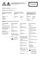
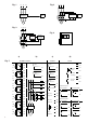
Fig. 1 Fig. 2 L1 L2 L3 1 1 5 3 825-MCM* 2 L1 L2 L3 4 5 825-MCM* CET 4 4 2 6 825-M* 6 M 3~ M 3~ Fig. 3 3 L1 L2 L3 1 T1 3 Fig. 4 5 2 T2 4 1 825-M* + 825-MST k l 825-MCM* 6 Σ M 3~ a) Fig. 5 825-MMV / 825-MLV PT 1T1 100 1T3 #1 1T2 PT 2T1 100 2T3 #2 2T2 PT 3T1 100 3T2 PT 4T1 #5 5T2 PT 6T1 100 6T3 1 3 5 #6 6T2 825-MCM* 7T2 A 4...
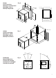
Fig. 6 (5- 13 8 7/1 6 +1 0 +1 / 0 16 ) (3 /8 ) max. 6 mm (1/4") max. 149 (5- 14/16) 110 (3/8) 10 Einbau Flush mounting Montage à encastrement Montaggio interno Montaje empotrado en-B AR TM OT OR MA NA GE R ua l ) 6 1 / 1 1 Set orde t Cha ng Se lec t e 14 Ent er Se 5 ( Rec Va lue s 4 ttin gs 137 (5- 3/8) Te s t (5 - Re 11 se t 6 /1 max.
Technische Änderungen vorbehalten 25.710.911-01 / 08.