
Instruction Manual
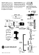


ADDING DASHPOT FLUID
-
(See note
Page 2) The dashpot fluid is shipped
separately. To add fluid, remove the core
and
dashpot
assembly by unfastening
the spring clamp. Remove the dashpot
cover by pulling the core straight out of
the dashpot Remove and discard red
plastic shipping spacer if present. Add
the silicone fluid with the dashpot cover
removed, with the piston and core in
place. Fill the dashpot to the top of the
three round projections on the piston.
See illustration below. The fluid must be
free of dirt or grit, and the dashpot and
piston must be absolutely clean.
Check fluid level periodically,
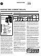
COIL CURRENT
-
The
maximum continuous current rating of the coil appears on the
relay nameplate. The current at which the relay is set to trip should not exceed this
value except when an additional device protects the coil against sustained overcur-
rent. To avoid relay damage, current through the relay coil must be interrupted after
the relay trips. Relay can carry rated continuous current in the non-tripped position
only.
OPERATING TIME ADJUSTMENT
-
Un-
less ordered with a specified time delay
setting, the relays are set for minimum
time delay when shipped. To increase
the time delay, remove the piston from
the dashpot and decrease the opening
of the adjustment valve by rotating its
cover counterclockwise. See illustration
below.
T
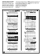
AC Calibrations
I
DC Calibrations
Coils
600V Max.
60 Hz Max.
Catalog
Number
q
A03A
A04A
A05A
A06A
A07A
A08A
A09A
A10A
A11A
A12A
A13A
A15A
A16A
A17A
A18A
A19A
810-A20A
A21A
A22A
A23A
A24A
81o-A25A
A26A
A27A
A28A
A29A
Coil
Current
Amps.
4
5
Part No.
2.3 2.8 X-67400
3.5 4.3 X-67404
4.7 5.7 X-67407
7.0 8.5 X-67415
10.5 12.8 X-67420
14.0 17.0 X-67425
18.6 22.7 X-67429
23.2 28.3 X-67433
33
40
47 57
X-67439
X-67444
56 68 X-67454
66
84
80
102
X-67457
X-67461
-
84 102 X-86996
01
16
123
141
X-86999
X87001
26
153 X-87002
51 184
X-67480
68
205 X-67479
51
184 X-88199
67
204
88
229
E%;
15
262 X-88196
50
305 X-88195
250
305 X-90713
300
367
X-90712
376
458
X-90711
502
612 X-90710
'55
920 X-90709
1.4
2.1
2.9
4.3
6.4
8.5
1 1.3
14.1
20
29
34
40
51
61
71
h
02
02
15
31
53
53
84
229
305
460
-
3
2
3
4
6
9
12
16
20
28
40
48
56
60
2.6 3.1
3.8 4.5
5.1 6.1
7.6 9.1
I
11.4 13.6
1.1 1.5
1.6 2.3
2.1 3.0
3.2 4.5
4.8 6.8
6.3 9.0
8.5 12.0
10.5 15.0
15 21
21 30
25 36
30
38
42
54
38 54
46 65
53 75
57 81
68 97
76 108
68 97
76
85
108
121
98 139
114 162
15.2 18.1
20.5 24.0
25.5 30.0
51
36 43
61
61 72
72 85
91 108
91 108
110 130
126
138
150
163
165 195
183 217
165 195
183
217
68
82
h
123
137
5
;:z
204
CAUTION: Do not attempt to
change the position of the check
valve cover, which holds the
steel balls of the check valve in
place.
61
68
76
87
102
102
204
245
306
405
615
216
259
320
320
320
274
325
328 390
411
547
488
650
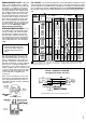
The range of operating times possible
with the Bulletin 810 is shown by the
time-current characteristics curves on
Page 2. Note that the curves cover all
possible combinations of two different
dashpot constructions and four different
fluids. Series A dashpot components
and Series A red and blue fluids are no
longer available, but can continue to be
used as indicated. Series B blue fluid is
supplied as standard. Higher viscosity
“clear” fluid will be supplied when
requested.
122
152
203
825 975 305
0
Catalog numbers are for single relavs in the ooen tvoe construction. with NC contacts and an automatic
-
reset. The calibration table
also
applies to catalog numbers beginning with the letter B, C, K, or L, and
ending with letter B. C. or D.
TYPICAL SCHEMATIC DIAGRAM
(See Applicable Codes and Laws)
Each area is bounded by curves that
represent the operating times with the
valve fully opened and fully closed. In-
termediate settings must be verified by
electrical tests.
Bulletin 810 Coils
Check
Valve
Three Bulletin 810 relays used for overload protection.
“Round Projections"