
User guide

CAUTION: Do not apply reverse energization during trial runs
until it has been determined that the speed switch contacts
in the reverse circuit are re-closing at a safe speed for the
particular application.
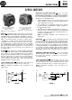
SPEED SENSING AND DIRECTION OF ROTATION
-
Turn adjusting
screw(s) out for lower speed, and in for higher speed sensing of
shaft. Adjust both screws when contacts are wired for sensing
shaft speed in each direction of rotation.
WIRING INSTRUCTIONS
-
Remove cover with nameplate, ex-
posing contact block. Use wire suitable for at least
90
C. Check
application notes for recommended wiring diagrams.
NOTE: Contact blocks are supplied with a common jumper
which may be removed if isolated contacts are desired. Replace
cover, torque cover screws 8-10 in.-lbs.
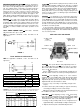
INTERCHANGEABLE MOUNTING BRACKETS
3 Point Flange
4 Point Flange
MOUNTING
-
Three types of interchangeable mounting brackets
are available for NEMA Type 1,4
and 13 speed switches. NEMA
Type 7
&
9 switches are available with base type mounting
bracket only. (See Table 3.)
Brackets, except on NEMA Type 7
&
9 switches, can be
mounted to the switch in any of eight positions, one position of
which is used to locate the conduit opening in the most
convenient position for the electrical connection. Bracket X-
268875 used on NEMA Type 7
&
9 switch is mounted in one
position. Mounting brackets are attached with four slotted
screws and lock washers.These screws should be torqued to
20-24 in.-lbs.
I
TABLE 3
-
MOUNTING BRACKETS
I
I
Oescriotion
1
Catalog Number 1
Base Mounting (NEMA Type 1, 4 and 13)
3 Point Flange Mounted
4 Point Flange Mounted
808-N1
808-N2
808-N3
Part Number
1 Base Mounting (NEMA Type 7 & 9)
I
X-268875
I
MAINTENANCE
-
Periodic inspection of the shaft seal is
suggested. If seal wear is evident, replace with external bearing
seal kit. Catalog Number
808-N5
Installation instructions are
included with replacement kit.
not attempt to disassemble the shaft assembly.
attempt may permanently damage the speed
Bearings are sealed and are of the permanently lubricated
type. In severe environments, such as cement dust, the shaft
seal should be cleaned and lubricated with “Anderol 757” or
equivalent. “Anderol 757” is a synthetic diester multi-purpose
grease.
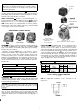
Lockout
Cover
Solenoid Fork
Speed Switch
With Lockout Solenoid
NEMA Type
1,
4
and 13 Enclosure
Exploded
View
of
Speed Switch with Lockout Solenoid
LOCKOUT SOLENOID
-
The Bulletin 808 can be equipped with a
lockout solenoid which consists of solenoid and cover
mounted on top of the switch. To add a lockout solenoid,
remove the top plate (4 screws) and mount the solenoid bracket
to the housing with two #10-32 x
yB”
screws provided. These
screws should be torqued to 20-24 in.-lbs. The lockout solenoid
fork must straddle the copper operating lever (see exploded
view). Mount cover as shown in exploded view with two #8--32 x
1” screws provided. Be sure the top plate gasket is in place
before torquing cover screws, 8-10 in.-lbs.
I
TABLE 4
-
LOCKOUT SOLENOID KITS
I
120 60 480 60
110 50 808-NLA1 440 50 808-N LA4
208 60 808-NLA20 600 60
240 60
220 50
TYPICAL LOCKOUT SOLENOID CONNECTIONS
(if used)
NOTE: See applicable standards, codes, and laws for all
applications.
MOTOR
T1
T2
To3
i::i
LO
FIGURE 5
3