DeviceNet Pendant Stations Bulletin 800E/F User Manual
Important User Information The illustrations, charts, sample programs, and layout examples shown in this guide are intended solely for purposes of example. Since there are many variables and requirements associated with any particular installation, Allen-Bradley does not assume responsibility or liability (to include intellectual property liability) for actual use based upon the examples shown in this publication. Allen-Bradley publication SGI-1.
Table of Contents Important User Information . . . . . . . . . . . . . . . . . . . . . . . . . . . . . . . . . . . 1 Preface This manual gives an overview of the Bulletin 800E/F DeviceNet™ Pendant Station and describes how to configure, install, operate and troubleshoot the device on the DeviceNet™ Network.. . . . . . . . . . . . . P-1 Intended Audience. . . . . . . . . . . . . . . . . . . . . . . . . . . . . . . . . . . . . . . . P-1 Contents of Manual . . . . . . . . . . . . . . . . . . . . . . . . . .
toc–ii Table of Contents Chapter 3 Installation and Mounting Chapter Objectives. . . . . . . . . . . . . . . . . . . . . . . . . . . . . . . . . . . . . . . . 3-1 DeviceNet™ Guidelines . . . . . . . . . . . . . . . . . . . . . . . . . . . . . . . . . . . . 3-1 Setting the Data Rate . . . . . . . . . . . . . . . . . . . . . . . . . . . . . . . . . . . 3-1 Setting the DeviceNet™ Node Address . . . . . . . . . . . . . . . . . . . . . . . . 3-2 Hanging the Pendant Station . . . . . . . . . . . . . . . . . . .
Table of Contents toc–iii Input/Output . . . . . . . . . . . . . . . . . . . . . . . . . . . . . . . . . . . . . . . . . . A-3 DeviceNet™ Connection. . . . . . . . . . . . . . . . . . . . . . . . . . . . . . . . . A-3 Communications . . . . . . . . . . . . . . . . . . . . . . . . . . . . . . . . . . . . . . . . . A-3 Data Rates . . . . . . . . . . . . . . . . . . . . . . . . . . . . . . . . . . . . . . . . . . . A-3 Distances . . . . . . . . . . . . . . . . . . . . . . . . . . . . . . . . . . . . . . . .
toc–iv Table of Contents Publication 800-UM001A-EN-P – June 2004
Preface Preface This manual gives an overview of the Bulletin 800E/F DeviceNet™ Pendant Station and describes how to configure, install, operate and troubleshoot the device on the DeviceNet™ Network. Intended Audience This manual is for the individuals responsible for installing, mounting and operating the 800E/F DeviceNet™ Pendant Station in an industrial environment.
P–2 Preface Contents of Manual This manual is organized as follows: Chapter 1 2 3 4 5 A Title Description Describes the purpose and contents of the manual Preface and the intended audience. Provides an overview of the 800E/F DeviceNet™ Overview Pendant Station and its features. Describes how to get the 800E/F DeviceNet™ Quick Start Pendant Station operating on the network.
Chapter 1 Overview of DeviceNet™ Pendant Station Chapter Objectives This chapter provides an overview of the DeviceNet™ Pendant Station and its features. It contains the following sections: Section Description Summary of Features Enclosure Features DeviceNet™ Connection Typical DeviceNet™ Configuration DeviceNet™ Components Replacement Parts Page 1-1 1-2 1-2 1-3 1-4 1-5 1-5 Description The 800E/F Pendant Station line offers a DeviceNet™ connection for applications where network communication is desired.
1–2 Overview of DeviceNet™ Pendant Station Summary of Features • Standard 800E/F legend carrier (800E-18xxxxxx or 800F-18xxxxxx) • Button guards to protect against inadvertent operation • Long life LED • Standard configurations • NEMA Type 4/4X/13 environmental rating • Easy installation and startup • DeviceNet™ connectivity • • Powered by DeviceNet™ • connection (no power supply • required) • Available with mini connector • Integral hanging bracket Auto baud Auto Device Replace Enabled
Overview of DeviceNet™ Pendant Station 1–3 DeviceNet™ Connection The DeviceNet™ Pendant receives all power and communications through the DeviceNet™ connection. A separate power supply is not required. This is the only external connection to the DeviceNet™ Pendant. The DeviceNet™ Pendant connects to the DeviceNet™ Network using a mini connector.
1–4 Overview of DeviceNet™ Pendant Station Typical DeviceNet™ Configuration A DeviceNet™ Network supports multiple Pendant devices and allows them to communicate with other network devices (up to 64). The DeviceNet™ Pendant operates on the network as a slave device. It does not initiate communications except for change-of-state, duplicate I/O messages and a node address check on power-up. The master writes data to, and receives data back from, the DeviceNet™ Pendant.
Overview of DeviceNet™ Pendant Station 1–5 DeviceNet™ Components DeviceNet™ Cables and components are available from Allen-Bradley as separate catalog numbers. It is your responsibility to install and implement the DeviceNet™ Network and supported devices according to the DeviceNet™ guidelines. Replacement Parts The DeviceNet™ Pendant stations come with all the parts required to install and use the product. The installer needs only to supply the mounting hardware and cabling.
1–6 Overview of DeviceNet™ Pendant Station Publication 800-UM001A-EN-P – June 2004
Chapter 2 Quick Start Chapter Objectives This chapter provides the necessary steps to get the DeviceNet™ Pendant Station operating on the network. It contains the following sections: Section Data Rate Configuration Node Address Configuration Connection to the Network Pendant Station Parameter Configuration Scanner Configuration Page 2-1 2-1 2-2 2-2 2-4 Data Rate Configuration This device is Auto Baud enabled. There is no need to configure data rate.
2–2 Quick Start Connection to the Network Wire the DeviceNet™ Pendant Station to an operating network. It will be connected with the mini connector. The device is fully powered by the network. For more information on system installation, please refer to the DeviceNet™ Cable System – Planning and Installation Manual (Publication DN-6.7.2). Pendant Station Parameter Configuration In order for proper operation, the parameters must be configured.
Quick Start 2–3 . Click on the Device Parameters tab.
2–4 Quick Start For more information on device configuration, please see Chapter 4 – Operations and the RSNetWorx for DeviceNet™ documentation. Scanner Configuration In order for proper operation, the scanner must be configured. The following graphics show the configuration of a 1756-DNB from the RSNetWorx for DeviceNet™ Software.
Quick Start 2–5 To access the Scanner Module Configuration screen from an Online view, double click on the 1756-DNB Scanner Icon.
2–6 Quick Start To access the Scanlist Editor, click on the Scanlist tab.
Quick Start 2–7 Add the 800E/F Pendant Station to the Scanlist. Select the Device in the Available Devices List. To have the software automatically assign the I/O addresses, select the Automap on Add selection box. Click on the “>” button.
2–8 Quick Start To view/edit I/O parameters, click on Edit I/O Parameters.
Quick Start 2–9 To view/edit the mapping of the Input data, select the Input tab.
2–10 Quick Start To view/edit the mapping of the Output data, select the Output tab.
Quick Start 2–11 To view/edit the auto device replacement parameters, click on the ADR tab. Select the Enable Auto-Address Recovery box. Click on Load Device Config. Select Configuration Recovery and Auto Address Recovery.
2–12 Quick Start For more information on scanner configuration, please refer to the DeviceNet™ Scanner Configuration Manual (Publication 1756-6.5.15 for the ControlLogix Platform, Publication 1747-6.5.2 for the SLC 500 Platform, or Publication 1711-6.5.118 for the PLC 5 Platform).
Chapter 3 Installation and Mounting Chapter Objectives This chapter describes how to install and mount a standard or custom DeviceNet™ Pendant Station.
3–2 Data Rate 125KB 250KB 500KB Autobaud Installation and Mounting Cable Length (Maximum) 500 m (1600 ft) 200 m (600 ft) 100 m (300 ft) See above, based on data rate of connected network Setting the DeviceNet™ Node Address The Node Address for the 800E/F Pendant Stations must be set through Node Commissioning. The factory default is Node 63. To set the DeviceNet™ Node Address: 1. Start RSNetWorx and select TOOLS from the Menu Bar. 2. Select Node Commissioning. The following screen will appear. 3.
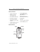
Installation and Mounting 3–3 DeviceNet™ Pendant Dimensions Figure 3.1 shows the dimensions of the Pendant Stations. Dimensions in millimeters (inches). Dimensions are not intended to be used for manufacturing purposes. Figure 3.1 Pendant Station Dimensions 149 (5.87) 60 (2.36) 81 (3.
3–4 Installation and Mounting Hanging the Pendant Station Dimensions in millimeters (inches). Dimensions are not intended to be used for manufacturing purposes. Figure 3.2 Pendant Mounting ∅6 (.24) Quick Disconnect Cordsets Standard 4-Pin Straight Quick Disconnect Cable-Mini DeviceNet™ 5-Pin Straight Quick Disconnect Cable-Mini Length Cat. No. Length Cat. No. 1.8 m 3.7 m 6.
Chapter 4 Operations Chapter Objectives This chapter contains the following sections: Section Modes of Operation Resetting the Device DeviceNet™ Operations Page 4-1 4-7 4-8 Modes of Operation The 800E/F DeviceNet™ Pendant Station has 3 operating modes: • Power-up/Reset Mode • Run Mode • Error Mode Power-up/Reset Mode During a power-up or reset, the 800E/F DeviceNet™ Pendant Station: 1. Clears output (turns output off). 2. Performs power-up diagnostic tests. 3.
4–2 Operations Run Mode After a successful power-up or reset, the 800E/F DeviceNet™ Pendant Station enters run mode and operates as a slave device to a master device. Configuration is done over the network using DeviceNet™ Manager or RSNetWorx for DeviceNet™ software. ON-DELAY TIMEBASE – Parameter 4 In normal operation, the device shall permit configuration of an on-delay timer for the input. The On-Delay timer is always enabled for debounce on inputs.
Operations 4–3 OFF-DELAY/ONE-SHOT TYPE – Parameter 6 In normal operation, the device shall permit configuration of an off-delay/one-shot timer for the input. The default value for Off-Delay/One-Shot Type is disabled. Value 0 1 2 3 Function Disabled One-Shot Not Supported Off-Delay OFF-DELAY/ONE-SHOT TIMEBASE – Parameter 7 In normal operation, the device shall permit configuration of the Off-Delay/One-Shot Timebase. The default timebase is 1 ms.
4–4 Operations OUTPUT VALUE – Parameter 9 In normal operation, the device shall permit output to be turned on and off. The default for the Output Value is Output Off. Value 0 1 Output Value Output Off Output On Important: If the device is connected to a master with I/O messaging, the I/O messaging will overwrite this command. OUTPUT FAULT ACTION – Parameter 11 In normal operation, the device shall permit configuration of the Output Fault Action.
Operations 4–5 OUTPUT IDLE ACTION – Parameter 13 In normal operation, the device shall permit configuration of the Output Idle Action. This tells the device what to do with the output in the case of an idle state. If Idle Value is selected, the device refers to parameter 14, Output Idle Value, for action on an idle state. The default for Output Idle Value is Idle Value.
4–6 Operations Control/Status Communications The I/O messaging is set up through client/server connections at power-up by the master device. Both Change-of-State (COS) and Strobe messaging connections are supported by this device. COS communications with the DeviceNet™ interface will consist of a single input byte and a single output byte. They are defined as below.
Operations 4–7 OUTPUT BYTE Bit Number 7 6 5 4 3 2 1 0 Function When = 1 N/A N/A N/A N/A N/A N/A N/A Output 1 Execute Function When = 0 N/A N/A N/A N/A N/A N/A N/A Output 1 Idle Error Mode Errors are critical and non-critical. Error Type Critical (non-recoverable) Non-Critical (recoverable) Description Failure of diagnostic tests during power-up/reset mode Duplicate node address detected I/O connection timeout See the troubleshooting chart in Chapter 5 for details on how to recover from an error.
4–8 Operations DeviceNet™ Operations The Allen-Bradley 1747-SDN, 1756-DNB, and 1771-SDN DeviceNet™ Scanner Modules are master devices on the DeviceNet™ Network. The 800E/F Pendant Station supports the Master/Slave Connection Set for master/slave communications on the DeviceNet™ Network.
Chapter Troubleshooting and Maintenance Chapter Objectives This chapter contains the following sections: Section Preventive Maintenance Using the LED Indicator Replacing a Pilot Light Lamp Page 5-1 5-2 5-3 Preventive Maintenance • Prevent accumulation of dust and dirt by: – keeping enclosure clean – keeping enclosure cover closed • Periodically check for loose connections. ! ATTENTION: To avoid shock hazard, remove incoming power before checking connections.
5–2 Troubleshooting and Maintenance Using the LED Indicator The LED provides status information on Pendant Station operations. The LED is visible when the enclosure cover is removed. The troubleshooting chart shows LED indications. It also shows how to use the LED to detect and correct common operating problems. LED Color State What It Means: Check DeviceNet™ power and cable connections and the power connection on the DeviceNet™ connector. Internal fault. Reset device.
Troubleshooting and Maintenance 5–3 The LED does not indicate the following malfunctions. Problem What It Means: Loose wiring Switch or button operators do Incorrect address not function. Faulty contacts, switch or button What To Do: Check wiring and cable connections. Check address setting via Network Who. Use an ohmmeter to verify opening/closing of contacts. Replacing a Pilot Light Lamp Pilot light lamps can be replaced easily by opening enclosure.
5–4 Troubleshooting and Maintenance ! ATTENTION: Before replacing the lens cap, be sure the lamp is seated properly or a short may result. 4. Replace the lens cap. 5. Check for proper operation.
Appendix A Specifications Mechanical Ratings Materials of Construction Table A.A Materials of Construction Part Description Enclosure Material PBT/PC Blend Thermo plastic Enclosure Gasket Nitrile 70 Durometer Shell – Nylon Insert – PVC Mini Connector Contact – Brass w/ Gold Flash Over Palladium Nickel Plating Gasket – Neoprene Shore ‘A’ Screws Stainless Steel AISI 304 800E/F Operators Misc. – See Industrial Control Catalog Shock and Vibration MECHANICAL SHOCK 1. Wave Shape – 1/2 cycle sine wave 2.
A–2 Specifications MECHANICAL VIBRATION 1. Axis Definitions – 3 mutually perpendicular axes 2. Frequency – 10…2000 Hz 3. Duration – 2 hours each axis 4. Maximum Allowable G Force: Operational 10 G Environmental Ratings Ingress Ratings All Units – Type 4/4X/13, IP66. Dependent upon rating of installed devices. Temperature Ratings Operating Temperature Storage Temperature -13° F…+131° F (-25° C…+55° C) -40° F…158° F (-40° C…+70° C) (185° F (85° C) Max.
Specifications A–3 Input/Output The voltage on I/O is 24V DC. 1 input and 1 output shall be supported. Most 800E/F operators will be supported. DeviceNet™ Connection A mini connector will be available. It consists of five 18 AWG wires for power and communications. Communications Data Rates 125 KB, 250 KB, and 500 KB Distances 500 m (1600 ft) 200 m (600 ft) 100 m (300 ft) 125 KB 250 KB 500 KB Certifications UL, CUL, and CE marked for all applicable directives.
A–4 Specifications Publication 800-UM001A-EN-P – June 2004
Publication 800-UM001A-EN-P – June 2004. . . . . . . . . . . . . . . . . . . . . . . . . . . Copyright 2004 Allen-Bradley Company, Inc.