
Instruction Manual

Rockwell Automation Publication RA-IN026A-EN-P – November 2009 1
Installation Instructions
Cover, Chassis and Leg Replacement Kits
(1)
For frame 5 drives with common bus.
Drive Frame Type 1 Cover Type 1 Chassis Type 1 Access Door Type 12 Cover Legs
2 SK-R1-CVR1-F2 SK-R9-CHSS1-F2 – SK-R1-CVR12-F2 –
3 SK-R1-CVR1-F3 SK-R9-CHSS1-F3 – SK-R1-CVR12-F3 –
4 SK-R1-CVR1-F4 SK-R9-CHSS1-F4 – SK-R1-CVR12-F4 –
5 SK-R1-CVR1-F5 SK-R9-CHSS1-F5 – SK-R1-CVR12-F5 –
SK-R9-CHSS2-F5
(1)
6 SK-R1-CVR1-F6 – SK-R1-AD1-F67 – SK-R9-LEG1-F6
7 SK-R1-CVR1-F7 – SK-R1-AD1-F67 – SK-R9-LEG1-F7
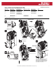
1
L1 L2 L3
O
I
DC+ DC–
0V
0V
3
4
2
6
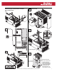
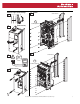
Frames 2 & 3 Type 1 Cover and Chassis
(Frame 2 shown)
(Frame 2 shown)
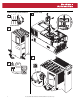
Manufacturing
Label
(1)
To receive a replacement Data Nameplate
label, contact U.S. Allen-Bradley Drives
Technical Support, (1) 262.512.8176, with the
serial number from the Manufacturing label
(see step 4 above for location).
Data
Nameplate
Label
(1)
5
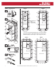
SK-R9-CHSS1-F2
SK-R9-CHSS1-F3
SK-R1-CVR1-F2
SK-R1-CVR1-F3