
Manual

Drive Installation 2-35
7000 “A” Frame 7000A-RM001A-EN-P – January 2011
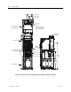
1000 [39.4]
700.00
[27.56]
209.6
[8.25]
Cable Entry Location
(Top)
480.5 [18.92]
366.2 [14.42]
251.9 [9.92]
480.5
[18.92]
1133.0
[44.61]
189.2 [7.45]
429.0 [16.89]
314.7 [12.39]
2314.6
[91.12]
Motor
Cables
U,V,W
Line
Cables
L1,L2,L3
SECTION A-ASECTION B-B
A
B
AB
1000 [39.4]
700.00
[27.56]
209.6
[8.25]
Cable Entry Location
(Top)
480.5 [18.92]
366.2 [14.42]
251.9 [9.92]
480.5
[18.92]
1133.0
[44.61]
189.2 [7.45]
429.0 [16.89]
314.7 [12.39]
2314.6
[91.12]
Motor
Cables
U,V,W
Line
Cables
L1,L2,L3
SECTION A-ASECTION B-B
A
B
AB
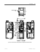
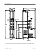
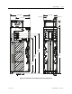
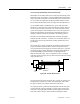
Figure 2.23 – Dimension Views of Cabling Cabinet for Configuration #1 without Input Starter