
Manual

2-18 Drive Installation
7000A-RM001A-EN-P – January 2011 7000 “A” Frame
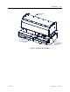
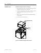
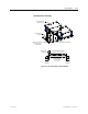
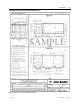
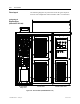
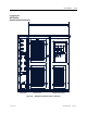
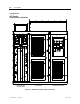
Drive Layout The following diagrams are presented to show the typical layout of
the three main configurations of the PowerFlex 7000 “A” Frame Drive.
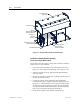
Converter Cabinet Control/DC Link/Fan Cabinet
Line Reactor/Starter
Cabling Cabinet
Figure 2.11 – Direct-to-Drive (AFE with DTD DC Link)
Configuration #1
Direct-to-Drive
(AFE with DTC DC Link)