
Manual

Component Definition and Maintenance 5-91
7000 “A” Frame 7000A-RM001A-EN-P – January 2011
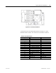
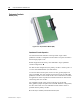
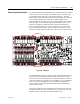
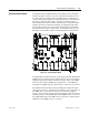
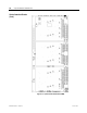
Figure 5.68 – Universal Encoder Board
Connections to the Universal Encoder Interface are made via a 1492-
IFM20F interface module. The connections to the IFM are as follows:
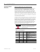
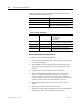
Table 5.G – Encoder Functions
IFM Pin # Quadrature Encoder Function Absolute Encoder Function
1 A1+ E0
2 A1- E1
3 B1+ E2
4 B1- E3
5 ENC_COM ENC_COM
6 Z1+ E4
7 Z1- E5
8 A2+ (Redundant or Dual ENC) E6
9 A2- (Redundant or Dual ENC) E7
10 ENC_COM ENC_COM
11 B2+ (Redundant or Dual ENC) E8
12 B2- (Redundant or Dual ENC) E9
13 Z2+ (Redundant or Dual ENC) E10
14 Z2- (Redundant or Dual ENC) E11
15 ENC_COM ENC_COM
16 ENC_COM ENC_COM
17 ENC_COM ENC_COM
18 ENC PWR (+12V) ENC PWR (+12V)
19 ENC PWR (+12V) ENC PWR (+12V)
20 ENC PWR (+12V) ENC PWR (+12V)