
Manual

Component Definition and Maintenance 5-71
7000 “A” Frame 7000A-RM001A-EN-P – January 2011
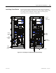
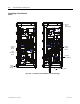
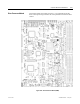
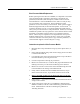
DC/DC Power Supply Description
The DC/DC power supply is used as a source of regulated DC voltages for
various logic control boards and circuits. The input to this power supply
is from a regulated 56V DC source.
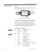
DC/DC
P o wer S upp l y
+
-
+5V - LOGIC
+/ -15V - LOGIC
56V DC
Chold-up
+/- 24 V - HECS
+24V - ISOLATO
R
+24 - XIO
Sense Cable
Figure 5.56 – DC/DC converter power supply
The capacitor at the input terminals is for power dip ride-through purposes.
Upon loss of the 56V input, the capacitors (C hold-up) will maintain the
voltage level. This component is not required in all configurations.
Due to the critical nature of the ACB/DPM Logic power source, the
DC/DC power supply has been designed to provide redundancy for the
+5V rail. There are two separate +5V outputs, each capable of powering
the logic boards. In the event of one failing, the other power supply will
be automatically switched in to provide the output power.
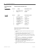
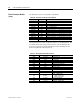
Terminal/Connections Descriptions
P1 – DC Input PIN NO. LABEL DESCRIPTION ONLY
1 +56V +56V input
2 +56V COMM +56V common
3 EARTH earth ground
P2 – SENSE
( To ACB )
PIN NO. LABEL DESCRIPTION ONLY
1 +56V +56V input supply
2 +56V RTN +56V input supply return
3 NC Not Connected
4 NC Not Connected
5 +24V Isolated +24V Supply
6 +24V RTN Isolated +24V Supply return
7 NC Not Connected
8 NC Not Connected
9 +5VA Primary +5V supply, before OR’ing diode
10 DGND(com1) +5V, +/-15V Common
11 +5VB Secondary +5V supply, before OR’ing diode
12 DGND(com1) +5V, +/-15V Common
13 ID0 Power Supply ID Pin 0
14 ID1 Power Supply ID Pin 1