
Manual

Component Definition and Maintenance 5-65
7000 “A” Frame 7000A-RM001A-EN-P – January 2011
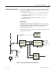
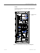
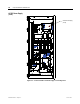
Terminal / Connections Descriptions (Pioneer Power Supply)
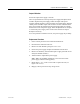
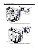
The terminal connections are shown below in Figure 5.50.
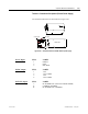
Control signals
DC outputs
Single phase input
TOP
VIEW
FRONT VIEW
Earth
Line
Neutral
Figure 5.50 – Terminal locations on AC/DC Pioneer power supply
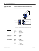
P1-AC input PIN# LABEL
1 EARTH
2 LINE
3 NEUTRAL
P2-DC output PIN# LABEL
1 +56V
2 +56V COMM
3 +56V
4 +56V COMM
P3-FAIL output PIN# LABEL
3 DC POWER FAIL (OUTPUT POWER GOOD)
15 CURRENT SHARING
14 DC POWER FAIL COMMON