
Manual

Component Definition and Maintenance 5-61
7000 “A” Frame 7000A-RM001A-EN-P – January 2011
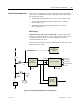
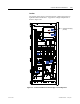
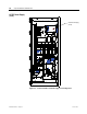
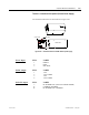
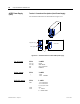
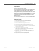
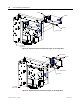
Figure 5.46 illustrates the control power distribution for AFE drives with
integral transformer and remote starter.
Printer O perator
Interface Relay s
DC/DC CONVERTER
VFD
A C/DC Converter
56V DC
1000W/1500W
+5V -LOGIC
+/ -15V-LOGIC
+/-24V- HE CS
+24V-ISO LA TO RS
+24-XIO
SENSE CABLE
20V
C Hold-up
Fan
20V Iso lated
Gate Dr iver
Power Supply
380V 50Hz
or
460V 60Hz
3- ph
DC Fai l
Customer
Supplier
120V
1- ph
Tx Fan
Line
Filter
Figure 5.46 – AFE Rectifier with Integral Isolation Transformer (Configuration #3)