
Manual

5-60 Component Definition and Maintenance
7000A-RM001A-EN-P – January 2011 7000 “A” Frame
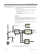
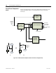
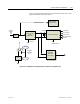
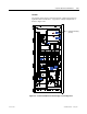
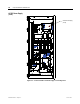
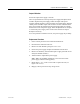
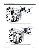
Figure 5.45 illustrates the control power distribution for AFE drives with
remote transformer/starter (A) or integrated line reactor with remote
starter (B).
-Pr inter
-O pe rator Interfac e
-Relays
DC/DC CONVERTER
AC/DC Converter
56V DC
1000W /1500W
+5V-LOGIC
+/-15V-LOGIC
+/-24V-HECS
+ 24V-ISOLATO RS
+24-X IO
SENSE CABLE
20V
CHold-up
20V Isol ated
Gate Driver
Power Supply
DC Fail
Customer
Suppli ed
120V
1- ph
VFD
Fan
380V 50Hz
or
460V 60Hz
3-ph
Line
Reac tor
Tx Fan
Fan
OR
B
A
VFD
Figure 5.45 – AFE Rectifier with Separate Isolation Transformer (Configuration #2)
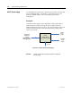
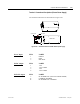
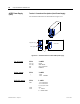
Control Power Components
(cont.)