
Manual

Component Definition and Maintenance 5-59
7000 “A” Frame 7000A-RM001A-EN-P – January 2011
Control Power Components There are two configurations in which control power will be distributed
for the drive. The different methods are dependent on what drive option
the customer has chosen:
1. AFE Rectifier with DTD DC Link – Conf. #1 (refer to Figure 5.44)
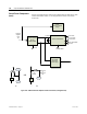
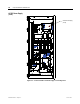
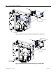
2. AFE Rectifier with Separate Isolation Transformer – Config. #2
(refer to Figure 5.45)
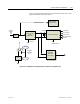
3. AFE Rectifier with Integral Isolation Transformer – Config. #3
(refer to Figure 5.45)
Ride-Through
Standard controls with 5 cycle ride-through – The drive main control
boards will remain energized for a total of 5 cycles after control power is
interrupted. If control power is not restored during the 5 cycles, a
controlled shutdown will occur.
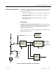
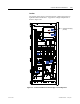
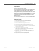
Figure 5.44 illustrates the control power distribution for AFE drives with
integral starter/line reactor.
Printer
O perator Interface
Relay s
DC/DC CO NVERTER
VFD
AC/DC Converter
56V DC
1000W/150 0W
+5V-LOGIC
+/ -15V-LOG IC
+/-24V-HECS
+24V-ISO LA TO R
S
+24-XIO
SE NSE CAB LE
20V
CHold-up
Fan
20V Isol ated
Gate Driver
Power Supply
38 0V 50Hz
or
46 0V 60Hz
3-ph
DC Fail
Fuse
Line
Reactanc e
120 V
1-ph
Figure 5.44 – AFE Rectifier with DTD DC Link (Configuration #1)