
Manual

Component Definition and Maintenance 5-33
7000 “A” Frame 7000A-RM001A-EN-P – January 2011
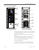
SGCT PowerCages
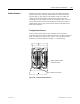
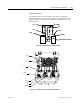
The snubber circuit is shown in Figure 5.26. Figure 5.30 shows the
physical locators of the same circuit. Measure the resistance across two
adjacent heatsinks. A value between 60 kΩ and 75 kΩ indicates a good
sharing resistor.
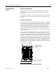
Cs-1
Cs-2
Anode
Rsn-2
Rsh
Rsn-1
Snubber Resistor Test Point
Cathode
Cs-1
Cs-2
Anode
Rsn-2Rsn-2
Rsh
Rsn-1
Snubber Resistor Test Point
Cathode
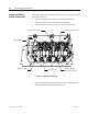
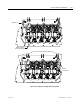
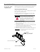
Figure 5.26 – Snubber Circuit for SGCT module
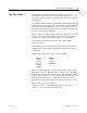
Rsh
Rsn-1
Cs-1
Cs-2
Anode
Cathode
Rsn-2
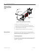
Figure 5.27 – Snubber Circuit Assembly for SGCT module