
Manual

5-30 Component Definition and Maintenance
7000A-RM001A-EN-P – January 2011 7000 “A” Frame
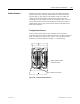
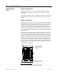
The snubber and sharing resistors are part of the resistor assembly located
behind the PowerCage.
1. Remove the PowerCage as outlined in “PowerCage Removal”.
2. Note the connection of the leads for correct replacement.
3. Detach the leads located on the bottom of the resistor assembly.
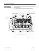
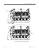
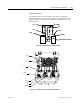
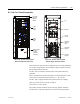
Snubber Capacitor
Sharing Resistor Connection
Snubber Resistor Connection
Cathode Connection
Common snubber and
sharing resistor connection
Anode Connection
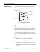
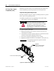
Figure 5.23 – Removal of Power Cage
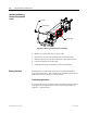
4. Remove the push nuts on the end of the retaining rod. Pinch the clip
together and pull off. Pull out the retaining rod.
Snubber and Sharing
Resistor Replacement