
Manual

Commissioning 4-87
7000 “A” Frame 7000A-RM001A-EN-P – January 2011
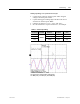
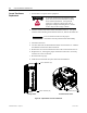
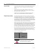
While performing a live synchronous transfer:
• Capture motor voltage at ACB test point “Vuv” & bypass
voltage at ACB test point “Vuvs”.
• Capture and trigger on falling edge of the DC Link current
waveform at ACB test point “Idc1”.
• Label the waveforms as “Vuv”, “Vuvs” and “Idc1”.
• Save the worksheet as “Synch on Motor 01”, for example.
Table 4.J – Oscilloscope Setting
Oscilloscope Time Base Waveform Test-Point
Waveform
Label
Ch. 1 DC Link Current Idc1 Idc1
Ch. 2 Motor Voltage Vuv Vuv
Ch. 3
10ms/div.
Bypass Line
Voltage
Vuvs Vuvs
Live Synchronous Transfer Capture (50Hz System)
Ch1: Idc1 (black), Ch2: Vuv (red), Ch3: Vuvs (blue)