
Manual

4-86 Commissioning
7000A-RM001A-EN-P – January 2011 7000 “A” Frame
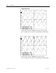
While simulating a synchronous transfer to determine the best lead
angle:
• Make sure the Diagnostic Trend has been setup and is armed.
• Capture motor voltage at ACB test point “Vuv” & bypass
voltage at ACB test point “Vuvs”.
• Capture and trigger on falling edge of the DC Link current
waveform at ACB test point “Idc1”.
• Label the waveforms as “Vuv”, “Vuvs” and “Idc1”.
• Save the worksheet as “Drift @ 15 Degree Lead Angle”,
for example.
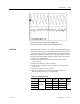
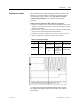
Table 4.I – Oscilloscope Setting
Oscilloscope Time Base Waveform Test-Point
Waveform
Label
Ch. 1 DC Link Current Idc1 Idc1
Ch. 2 Motor Voltage Vuv Vuv
Ch. 3
10ms/div.
Bypass Line
Voltage
Vuvs Vuvs
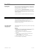
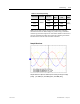
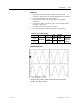
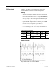
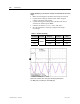
Synchronous Transfer Test to verify Sync Lead Angle (50Hz System)
Ch1: Idc1 (black), Ch2: Vuv (red), Ch3: Vuvs (blue)