
Manual

Commissioning 4-83
7000 “A” Frame 7000A-RM001A-EN-P – January 2011
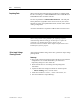
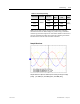
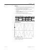
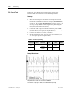
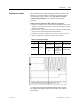
Sample waveforms of DC Test recorded on 18-Pulse Drive
Idc Cmd Test = 0.5pu [Ch1: Vdcr1, Ch2: Idc1 at ACB test points]
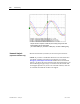
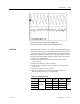
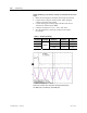
Load Test After autotuning of the drive, run the motor on load and capture the
following waveforms at 50% load and at 100% load. If the system is
not ready for 100% load test, then capture the waveforms at the max
load you are allowed to run the drive at. Also, print variables at 50%
and 100% load points. Before printing variables make sure the drive
Access Level is at SERVICE.
• Capture line voltage & current waveforms at ACB test points
“V2uv” & “I2u”.
• Label the waveforms as “V2uv” and “I2u”.
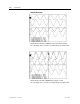
• Capture motor voltage & current waveforms at ACB test points
“Vuv” & “Iu”
• Label the waveforms as “Vuv” and “Iu”.
• Save the worksheet as “Line and Load Voltage and Current
Waveforms at 1048 rpm, 31 A”, for example.
Table 4.G – Oscilloscope Setting
Oscilloscope Time Base Waveform
Test-
Point
Waveform
Label
Sheet
Name
Ch. 1 Line Voltage V2uv V2uv
Ch. 2 Line Current I2u I2u
Ch. 3 Motor Voltage Vuv Vuv
Ch. 4
10ms/div.
Motor Current Iu Iu
[see
above]