
Manual

4-82 Commissioning
7000A-RM001A-EN-P – January 2011 7000 “A” Frame
DC Current Test Perform DC Test. Refer to the commissioning section of the
PoweFlex7000 user manual for a more detailed procedure.
Summary:
• Make sure the Diagnostic Trend has been setup and is armed.
• Run the DC Test with Idc Command Test (P119) set to 0.1pu.
Increase Idc Command Test from 0.1 0.3pu (for AFE drives)
or from 0.1 0.7pu (for 18-pulse drives) in steps of 0.1pu. At
each step, verify DC link current regulation by monitoring Idc
Error (P323) and Alpha Line (P327).
• Capture DC link voltage waveform at ACB test point “Vdcr1”
and DC link current waveform at ACB test point “Idc1” at 0.3pu
(for AFE drives) or at 0.7pu (for 18-pulse drives).
• Label the waveforms as “Vdcr1”, and “Idc1”.
• Save the worksheet as “DC Test @ 0.3pu” (for AFE drives) or
“DC Test @ 0.7pu” (for 18-pulse drives).
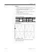
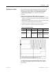
Table 4.F – Oscilloscope Setting
Oscilloscope
Time
Base
Waveform
Test-
Point
Waveform
Label
Sheet
Name
Ch. 1
DC Link
Voltage
Vdcr1 Vdcr1
Ch. 2
2ms/div.
DC Link
Current
Idc1 Idc1
DC Test
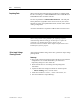
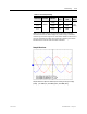
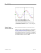
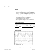
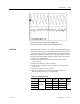
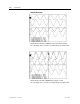
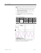
Sample Waveforms:
Sample waveforms of DC Test recorded on a AFE Drive
Idc Cmd Test = 0.2pu [Ch1- Vdcr1, Ch2 – Idc1 at ACB test points]