
Manual

Commissioning 4-81
7000 “A” Frame 7000A-RM001A-EN-P – January 2011
Summary:
• Drive input contactor should be closed. If the drive input
contactor configuration is set to NOT RUNNING, you will have
to temporarily change it to ALL FAULTS.
• Ensure that the drive is not running when capturing these
waveforms.
• Capture line voltage at ACB test point “V2uv” and line current
at ACB test point “I2u”.
• Label the waveforms as “V2uv”, and “I2u”.
• Save the worksheet as “Harmonics (Drive Not Running)”.
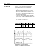
Table 4.E – Oscilloscope Setting
Oscilloscope Time Base Waveform
Test-
Point
Waveform
Label
Sheet Name
Ch. 1
Line
Voltage
V2uv V2uv
Ch. 2
10ms/div.
Line
Current
I2u I2u
Harmonics
(Drive Not
Running)
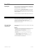
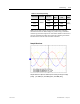
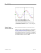
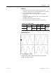
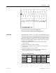
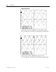
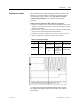
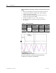
Sample Waveforms
Sample waveforms captured on SCBL test points under Drive Not Running
Condition [Ch1: V2uv, Ch2: I2u]