
Manual

4-62 Commissioning
7000A-RM001A-EN-P – January 2011 7000 “A” Frame
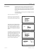
7. Record the value of the rectifier input voltage by looking at
parameter Rec Input Voltage (P696). Let this value be V
in1
.
8. The value of input impedance for AFE drives is calculated as
follows:
drivesfor
VVCI
VV
L
ininindc
inin
in
PWM
)(
10
10
⇒
−+
−
=
C
in
is the value of input filter capacitor given by Line Filter Cap
(P133)
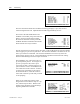
9. The value of input impedance for SCR drives is calculated as
follows:
drivesSCRfor
I
VV
L
dc
inin
in
)(3
10
⇒
−
=
10. Stop the drive. Set parameters Operating Mode to Normal and
Idc Command Test to zero.
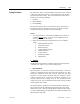
T DC Link (P#115) Manual Tuning
An appropriate value for the T DC Link parameter can be determined
from the current regulator step response while operating in DC
Current test mode. The following procedure should be followed:
1. Be sure that all the parameters in the Drive Hardware and Motor
Ratings groups have been set to the correct values. Otherwise,
the calculated value of parameter T DC Link in Current Control
will not be correct.
2. Set parameter Operating Mode in the Feature Select to DC
Current to enter dc current test mode.
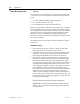
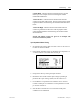
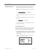
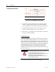
Current Control Parameter Screen
Tuning Procedure (cont.)