
Manual

Commissioning 4-39
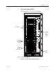
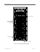
7000 “A” Frame 7000A-RM001A-EN-P – January 2011
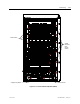
DC/DC Converter (PS2)
The DC/DC converter has no provision for output power
adjustments. A green LED on front case of the power supply
indicates that the power supply is functioning properly. Using a
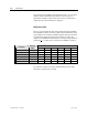
Digital Multimeter, measure each of the outputs of the DC/DC
converter to ensure that they meet the values specified on the
electrical schematics. Compare these measured values to those
displayed on the Operator Terminal under the Metering group.
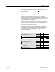
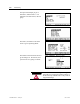
Plug 1 (P1) – INPUT
Terminal Numbers Description Value
1 2 Input Power (+56 V)
Plug 2 (P2) – SENSE SIGNAL
Terminal Numbers Description Value
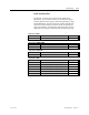
Plug 3 (P3) – ISOLATOR
Terminal Numbers Description Value
1 2 ISOLATOR (+24V,1A)--ISOL_COMM (COM4) ±5%
Plug 4 (P4) – PWR
Terminal Numbers Description Value
1 2 +24V_XIO (+24V,2A)--XIO_COMM (COM3) ±5%
3 4 +HECSPWR (+24V,1A)--LCOMM (COM2) ±1%
5 4 -HECSPWR (-24V,1A)—LCOMM (COM2) ±1%
6 7 +15V_PWR (+15V,1A)—ACOMM (COM1) ±0.5V
8 7 -15V PWR (-15V,1A)--ACOMM (COM1) ± 0.5V
9 10 +5V PWR (+5V,5A)--DGND (COM1) 5.1-5.5V