
Manual

Commissioning 4-35
7000 “A” Frame 7000A-RM001A-EN-P – January 2011
Control Power Tests
I M P O R T A N TI M P O R T A N T
Prior to energizing the drive, verify that the
control power being fed into the input breakers
is rated as designated on the electrical diagram.
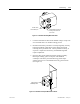
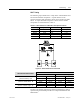
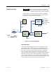
Although there are a variety of options available to customers
that will effect the control power distribution within the drive,
the input will always be as illustrated below:
20V
ISOLATED
GATE DRIVER
POW ER SUPPLY
Single Phase
AC /DC
Converter
56V
1000W or
150 0W
+5V-LOGIC
+/-15 V-LOGIC
+/-24V-HECS
+24V-ISOLATORS
+24V-XIO
20V
DC/DC
CO NVERTER
Fan
SENSE
CAB LE
DC Fail
120V
Single
phas e
G rounded
Neutral
CB 1
Custom er
s upplie d
3-ph
Chold-up
CP T1
Op tiona l
1- ph
&
Remote
I/O
PV550
Figure 4.8 – Control Power Distribution
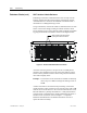
Three-Phase Input
In the 3-phase input configuration, the customer supplies 3-phase
control power into the Disconnect Switch (Labeled DS1 on the
Electrical Schematics). From that point, the power is distributed to
the 3-phase fan and to the power supplies through a single phase
CPT. The output of the single phase CPT powers all the power
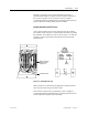
supplies and controls within the drive. The 3-phase control should be
measured at the input to DS1. If the rating matches the designation
on the electrical schematic, it is acceptable to apply control power to
the drive. Take necessary measures to rectify the control power level
in the event that it does not meet the design specifications.