
Manual

Commissioning 4-31
7000 “A” Frame 7000A-RM001A-EN-P – January 2011
SGCT Testing
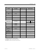
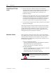
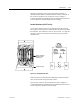
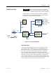
The following steps outline how to verify SGCT semiconductors and
all associated snubber components. A quick reference to the
expected resistance and capacitance values can be found in the table
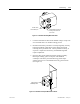
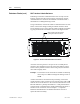
below. A simple schematic in Figure 4.3 shows how the snubber
components are connected across a SGCT.
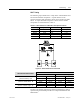
Table 4.A – SGCT Snubber Circuit Resistance and Capacitance Values
SGCT Rating Sharing Resistor Snubber Resistor Snubber Capacitor
1500 Amp 80 kΩ 6 Ω (AFE Rectifier) 0.2 µf
1500 Amp 80 kΩ 7.5 Ω (Inverter) 0.2 µf
800 Amp 80 kΩ 10 Ω 0.1 µf
400 Amp 80 kΩ 15 Ω (AFE Rectifier) 0.1 µf
400 Amp 80 kΩ 17.5 Ω (Inverter) 0.1 µf
2300V drives will not have a sharing resistor on devices.
Figure 4.4 – SGCT Snubber Circuit Connections
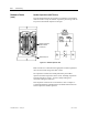
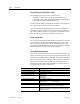
Measured Resistance
SGCT Resistance Measurement
Inverter Rectifier (AFE only)
SGCT Anode-Cathode Resistance
(Heatsink to Heatsink) k-Ω
(Lowest) (Highest) (Lowest) (Highest)
Snubber Resistance
(Test Point – Heatsink above) Ω
(Lowest) (Highest) (Lowest) (Highest)
Snubber Capacitance
(Test Point – Heatsink on Right)
µF
(Lowest) (Highest) (Lowest) (Highest)
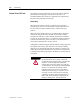
If a device or snubber component is found to be damaged, it must be
replaced using the detailed procedures in Component Definition and
Maintenance.