
Owner manual

Drive Installation 2-19
7000 “A” Frame 7000A-UM151D-EN-P – March 2013
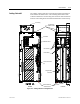
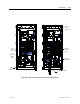
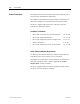
Cabling Cabinet #3 The cabling cabinet of the drive with integral isolation transformer is
located in the left-hand section. The mounting and location of the
isolation transformer is shown along with customer cable termination
locations. The cooling fan for the isolation transformer is located on top.
Top Cable Entry
and Exit locations
Ground Bus
Hall Effect Sensors
Line Terminals
Load Terminals
Integral Isolation
Transformer
Current Transformers
(CT)
Bottom Cable Entry
and Exit locations
Side View Front View
(Front)
(
B
a
c
k)
F
an Ho
u
s
i
n
g
Figure 2.14 – Cabling Cabinet for Configuration #3