
Owner manual

Drive Installation 2-13
7000 “A” Frame 7000A-UM151D-EN-P – March 2013
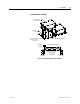
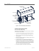
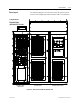
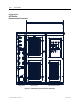
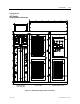
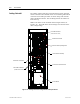
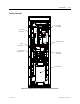
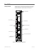
Drive Layout The following diagrams are presented to show the typical layout of
the three main configurations of the PowerFlex 7000 “A” Frame Drive.
Converter Cabinet Control/DC Link/Fan Cabinet
Line Reactor/Starter
Cabling Catinet
Figure 2.8 – Direct-to-Drive (AFE with DTD DC Link)
Configuration #1
Direct-to-Drive
(AFE with DTC DC Link)