
Owner manual

4-4 Component Definition and Maintenance
7000A-UM151D-EN-P – March 2013 7000 “A” Frame
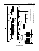
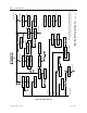
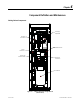
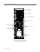
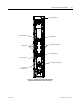
Top Cable Entry
and Exit locations
Ground Bus
Hall Effect Sensors
Line Terminals
Load Terminals
Integral Isolation
Transformer
Current Transformers
(CT)
Bottom Cable Entry
and Exit locations
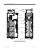
Side View Front View
(Front)
(
Back)
F
an Hou
s
ing
Figure 4.4 –Cabling Cabinet for Configuration #3
(AFE Rectifier with Integral Isolation Transformer)