
Manual

Drive Installation 2-11
7000 “B” Frame 7000-UM150I-EN-P – June 2013
Cabinet Layout and
Dimensional Drawings
of Drive
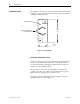
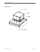
The following drawings are generic in nature and will not accurately
detail your drive. They are provided here to give you a general
overview of a typical drive.
The Dimensional Drawings are order specific and will show the
information outlined.
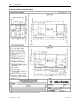
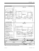
The dimension drawing provides important information for the
installation of the equipment.
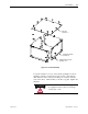
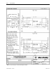
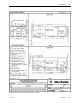
The FLOOR PLAN shows:
• the locations for anchoring the equipment to the floor (balloon D)
• size and location of openings for bottom power cable entry
(balloons A and B)
• size and location of openings for bottom control wiring entry
(balloon C)
• size and location of openings for bottom fan power wiring entry
(balloon J)
The ROOF PLAN shows:
• size and location of openings for top power cable entry (balloons
A and B)
• size and location of openings for top control wiring entry
(balloon C)
• size and location of openings for top fan power wiring entry
(balloon J)
• minimum aisle clearance in front of equipment (balloon M)
The Front View shows:
• minimum clearance required at top of drive for fan maintenance
(balloon K)