
Manual

Troubleshooting 7-31
7000 “B” Frame 7000-UM150I-EN-P – June 2013
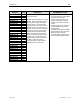
WARNING
MESSAGE
WARNING
CODE
DESCRIPTION
RECOMMENDED ACTIONS
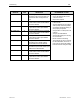
Air Filter
29
The Pressure drop at the input to the
converter section sensed by the pressure
transducer (as a voltage) has dropped
below the value set in Pressure Value Alarm
(P320). This is dependent on the operation
of the Main Cooling Fan.
– Verify fan rotation
– Check for blocked airflow in the filters/
heatsinks/ ducting (if installed) – Clean as
required
– Improper Alarm settings – Verify Pressure
Value voltage level when running with
clear air flow, and compare to expected
values for that specific drive type
– Verify Alarm and Trip set-up procedure
was completed adequately and adjust as
necessary
– Verify for drives with external ducting that
there is sufficient air to the drive input
– Verify supply voltage to differential
pressure transducer, and confirm output
is stable
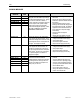
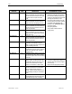
Autotune TimeLmt
53
Indicates that the autotune test could not
measure the parameter in the allotted time.
– REFER TO THE POWERFLEX 7000
SERIES B MANUAL (CHAPTER 4 –
COMMISSIONING) ON AUTOTUNE
PROCEDURES, RESULTS, AND
ACTIONS
Auxiliary Prot’n
71
Standard External Fault/Warning Input
included to allow the end-user to install a
protective relay/system status contact that
can activate a drive fault or warning,
depending on configuration of Aux Prot
Class (P445)
– See associated Fault Description
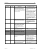
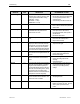
Bus Transient
123
The drive has detected a transient of rapid
loss of line, and has placed both bridges in
freewheel mode until event clears.
– Check system for capacitive switching
events
– Contact factory for detailed actions
Buss Fault Line
200
DEVELOPMENT ERROR – NOT ACTIVE
–
Buss Fault Motor
194
DEVELOPMENT ERROR – NOT ACTIVE
–
Buss Flt Ext Mem
162
DEVELOPMENT ERROR – NOT ACTIVE
–
Buss Flt FPGA
161
DEVELOPMENT ERROR – NOT ACTIVE
–
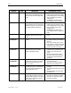
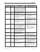
Bypass OV
184
The measured Line-Side Bypass Voltage
has exceeded Line Overvoltage Trip (P165)
for the duration set in Line Overvoltage
Delay (P166).
– Verify the parameters are set properly
– Check for possible line voltage
transients
– Verify VSB connections and tap settings,
resistor values, and grounds
– If voltage is too high, change tap
settings on the input source to lower
voltage to an acceptable level
Bypass Rvs Rotn
187
The phase sequence on the voltage
measured on the primary side of the Bypass
Contactor is not the same as the phase
sequence on the output of the drive.
– The drive will not allow a synchronous
transfer unless the phasing is the same
– Confirm the phase sequences and swap
cables if necessary