
Manual

Component Definition and Maintenance 6-77
7000 “B” Frame 7000-UM150I-EN-P – June 2013
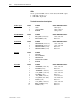
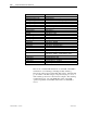
P6-SCBM PIN# LABEL DESCRIPTION ONLY
1 +LEMPWR (+24V,1A) +24V,1A/com2
2 LCOMM (com2) 0V/com2
3 –LEMPWR (-24V,1A) -24V,1A/com2
4 +15V_PWR (+15V,1A) +15V,1A/com1
5 ACOMM (com1) 0V/com1
6 –15V_PWR (-15V,1A) -15V,1A/com1
7 +5V_PWR (+5V,10A) +5V,10A/com1
8 DGND (com1) 0V/com1
9 +15V_ENC (+15V,1A) +15V,1A/com3
10 ENC_COMM (com3) 0V/com3
11 DGND (com1) 0V/com1
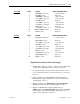
P7-CIB PIN# LABEL DESCRIPTION ONLY
1 XIO_PWR (+24V,3A) +24V,3A/com5
2 XIOCOMM (com5) 0V/com5
3 +15V_PWR (+15V,1A) +15V,1A/com1
4 ACOMM (com1) 0V/com1
5 –15V_PWR (-15V,1A) -15V,1A/com1
6 +5V_PWR (+5V,10A) +5V,10A/com1
7 DGND (com1) 0V/com1
8 +SCNPWR (+12V,1A) +12V,1A/com1
9 SCNCOMM (com1) 0V/com1
10 DGND (com1) 0V/com1
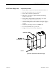
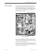
Replacement Procedure for DC/DC Power Supply
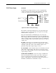
1. With the drive energized, check to see if the indicator light is ON
or OFF. If it is OFF, replacement is necessary. (View 1)
2. De-energize the drive, isolate and lock out the 3-phase control
power, and remove all wire connections from the top of the unit.
(View 1)
3. Remove quantity of (4) M6 (H.H.T.R.S.) that will allow the
DC/DC Power Supply Assembly to be removed from the Low
Voltage Panel. (View 1)
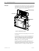
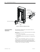
4 Remove quantity of (4) M4 (P.H.M.S.) and Nylon Shoulder
Washers from the back of the Mounting Plate. (View 2)
5. Replace old DC/DC Power Supply with the new one.
NOTE: Make sure the Black Insulation is between the DC/DC
Power Supply and the Mounting Plate. Repeat Steps 4, 3, 2, 1
in this order to replace unit. (View 2)