
Manual


6-70 Component Definition and Maintenance
7000-UM150I-EN-P – June 2013 7000 “B” Frame
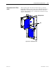
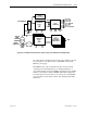
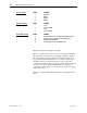
P1-AC input PIN# LABEL
1 EARTH
2 LINE 1
3 LINE 2
4 LINE 3
P2-DC output PIN# LABEL
1 +56V
2 +56V COMM
3 +56V
4 +56V COMM
P3-FAIL output PIN# LABEL
3 DC POWER FAIL (OUTPUT POWER GOOD)
14 AC/DC FAIL COMM (LOGIC RETURN)
15 CURRENT SHARING
16 AC POWER FAIL (POWER FAIL)
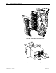
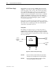
Ensure the output of the supply is 56V DC.
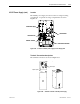
There is a potentiometer on the top of the power supply that adjusts
the 56 Volt DC output for the power supply. Isolate the output of
the power supplies; multiple supplies in parallel will affect your
measurements. With the control power on and the output of the
AC/DC Converter isolated from the drive control, adjust the
potentiometer until the output equals 56 volts DC. Perform this test
on each power supply. When all adjustments are complete, re-
connect the power supply to the circuit and re-measure the output.
Adjust if necessary.
If it is not possible to maintain 56 V DC, the power supply may be
faulty.