
Manual

6-54 Component Definition and Maintenance
7000-UM150I-EN-P – June 2013 7000 “B” Frame
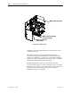
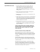
D.C. Link and Fan Cabinet Components
AC/AC
Converters
3-phase
fan power
transformer
Ground Bus
“Hold up” Capacitor
DC Link Inductor
(Barrier removed)
Fan Power Cable
Entry (bottom)
Impeller Access
Panel
Fan
Inlet Ring
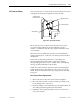
Figure 6.40 – DC Link and Fan cabinet
with control panel shown
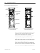
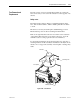
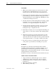
Figure 6.41 – DC Link and Fan Cabinet
with fan control panel removed
The door of the cabinet is interlocked such that it cannot be opened
unless the fan power is disconnected. The fan power disconnect
handle is mounted on the right-hand side of the cabinet.
When the door is opened, fan control components are accessible.
Behind the fixed fan control panels is the medium voltage
compartment where the DC link and fan are located.
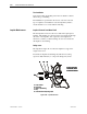
The D.C. link is mounted on the floor plate of the cabinet. Airflow
barriers are assembled around the coils of the inductor to direct a
portion of the cooling air through the inductor.
Power connections are made to the inductor via its flexible leads.
There are four power connection points labeled L+, L-, M+, and M-.
The iron core of the D.C. link is equipped with thermal protection.