
Manual

6-20 Component Definition and Maintenance
7000-UM150I-EN-P – June 2013 7000 “B” Frame
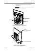
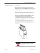
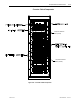
Converter Cabinet The converter cabinet contains three rectifier modules and three
inverter modules. Figure 6.14 shows a 2300-volt converter with a
Pulse Width Modulation Rectifier (PWMR).
Isolated Gate Driver Power Supplies (IGDPS) are mounted on the
cabinet‟s right side sheet.
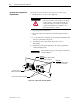
Thermal sensors are installed on the top module of the inverter and
rectifier. The exact location depends on the drive configuration.
These sensors are connected to Temperature Feedback Boards,
which bring the signals back to the drive control.
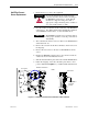
PowerCage™ A PowerCage is a converter module, consisting of the following
elements:
• epoxy resin housing
• power semi-conductors with gate driver circuit boards
• heatsinks
• clamp
• snubber resistors
• snubber capacitors
• sharing resistors
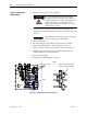
All drives have six PowerCages: three rectifier modules and three
inverter modules. There are three types of rectifiers: 6-pulse PWMR,
6-pulse SCR, and 18-pulse SCR.
6-pulse PWMR type rectifiers use SGCTs as semi-conductors.
6-pulse SCR, and 18-pulse SCR rectifiers use SCRs as semi-conductors.
All inverter modules use SGCTs as semi-conductors.
The size of the PowerCage will vary depending on the system
voltage, and the components will also vary in the system current.