
Manual


5-2 Functional Description
7000-UM150I-EN-P – June 2013 7000 “B” Frame
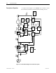
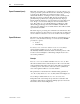
Description of Operation A complete block diagram of the PF7000 control circuit is shown
below. The major blocks are described in the following sections.
Motor
Motor
Model
Line
Protection
Machine
Converter
Line
Converter
DC Link
inductor
Motor filter
cap
Machine side
feedback and
gating
Line side feedback
and gating
Flux angle
Alpha
machine
Ix command
Iy command
Line filter
cap
AC Line
reactor
Idc Feedback
Line voltage
Source
Tach
Feedback
Slip freq
Stator freq
Speed
Control
Sync
Transfer
Flux
Control
Current
Control
Alpha
line
Machine
Protection
Line
current
Motor
voltage
Motor
current
Speed feedback
Flux feedback
Faults
Faults
Speed
Reference
Speed
Command
Motor
Motor
Model
Line
Protection
Machine
Converter
Line
Converter
DC Link
inductor
Motor filter
cap
Machine side
feedback and
gating
Line side feedback
and gating
Flux angle
Alpha
machine
Ix command
Iy command
Line filter
cap
AC Line
reactor
Idc Feedback
Line voltage
Source
Tach
Feedback
Slip freq
Stator freq
Speed
Control
Sync
Transfer
Flux
Control
Current
Control
Alpha
line
Machine
Protection
Line
current
Motor
voltage
Motor
current
Speed feedback
Flux feedback
Faults
Faults
Speed
Reference
Speed
Command
Figure 5.1 – Functional Block Diagram of PF 7000 control system