
Manual

4-38 Commissioning
7000-UM150I-EN-P – June 2013 7000 “B” Frame
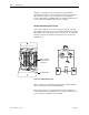
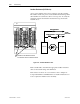
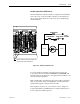
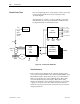
Snubber Resistance (SCR Device)
Access to the snubber resistor is not required to test the resistance.
The snubber circuit test point is located within the PowerCage under
the heatsinks. For each device, there is one test point. To verify the
resistance, measure the resistance between the test point and the
heatsink above.
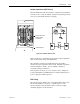
Resistance value between Test Point
and heatsink to its left is snubber resistance
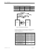
Sharing Resistance
Snubber Resistance
Snubber Capacitor
Testpoint
To Gate
Driver Board
HeatsinkHeatsink
Sharing Resistance
Snubber Resistance
Snubber Capacitor
Testpoint
To Gate
Driver Board
HeatsinkHeatsink
Figure 4.11 – Snubber Resistance Test
Refer to Table 4.B to determine the appropriate snubber resistance
value for the current rating of the SCR used.
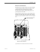
If the resistor is found to be out of tolerance, refer to Chapter 6 –
Component Definition and Maintenance for detailed instructions on
how to replace the snubber resistor assembly.