
Manual

3-78 Operator Interface
7000-UM150I-EN-P – June 2013 7000 “B” Frame
MainMenu:
Diagnostics:
F9-Diags
Setup:
F8-Setup
P
F8-Access
Diag View:
F9-View
Continued from Page 1
Access:
F10-Access
P
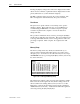
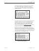
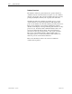
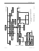
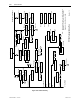
PF7000 Terminal Menu Tree
Note: All screens have access to the F1-Help and
F6-Alarm key. They are not shown on the
diagram in order to improve clarity.
Page 2 of 2
Diag Setup:
F8-D Setup
ST
Q
R
Password Change
F9-Change
Alarm Summary:
Faults: Warnings:
A
F6-Alarms
F9-Faults F8-Warning
Fault Help:
Display Group: Display: View Parameter:
F4-Display
Q
R
Display Custom:
F7-Custom
ST
TD M
F7-Modify
Language:
F9-Lang'ge
P
F8-Access
Modify Parameter
P
F8-Access
MST
Parameters
External Setup:
External Text
Fault Masks
PLC
Analog
Memory
Obtain Database
Communications
Protocol Analyzer
F7-Analyze
Faults Setup:
Faults Overview:
F7-Overvw
F7-Toggle
F10 & <
F10 & ^
F10 &
PLC Setup:
F8-Toggle
TS
Analog Setup: TS
XIO
XIO Setup:
Setup Wizard
Q
R
Message:
F10-Exit
E
F9-NoF8-Yes
^
Figure 3.105 – Menu Hierarchy