User Manual PowerFlex 7000 HMI Offering With Enhanced Functionality Publication Number 7000-UM201B-EN-P
Important User Information Read this document and the documents listed in the Additional Resources section about installation, configuration, and operation of this equipment before you install, configure, operate, or maintain this product. Users are required to familiarize themselves with installation and wiring instructions in addition to requirements of all applicable codes, laws, and standards.
Table of Contents Preface Introduction. . . . . . . . . . . . . . . . . . . . . . . . . . . . . . . . . . . . . . . . . . . . . . . . . . . . . . . 5 Basic Configurations . . . . . . . . . . . . . . . . . . . . . . . . . . . . . . . . . . . . . . . . . . . . . . . 5 Remote-mounted HMI . . . . . . . . . . . . . . . . . . . . . . . . . . . . . . . . . . . . . . . . . 5 Locally-mounted HMI. . . . . . . . . . . . . . . . . . . . . . . . . . . . . . . . . . . . . . . . . . 5 No HMI supplied . . . . . . . . . .
Table of Contents Common Panel . . . . . . . . . . . . . . . . . . . . . . . . . . . . . . . . . . . . . . . . . . . . . . . . . . Change the Access Filter . . . . . . . . . . . . . . . . . . . . . . . . . . . . . . . . . . . . . . Change the Access Password. . . . . . . . . . . . . . . . . . . . . . . . . . . . . . . . . . . Change the ReadWrite Filter . . . . . . . . . . . . . . . . . . . . . . . . . . . . . . . . . . Search for Parameter . . . . . . . . . . . . . . . . . . . . . . . . . . . . . . . . .
Table of Contents Chapter 6 System Updates Overview . . . . . . . . . . . . . . . . . . . . . . . . . . . . . . . . . . . . . . . . . . . . . . . . . . . . . . . . Chapter Objectives. . . . . . . . . . . . . . . . . . . . . . . . . . . . . . . . . . . . . . . . . . . . . . . Using an FTP Client to Update Firmware. . . . . . . . . . . . . . . . . . . . . . . . . . Drive Firmware . . . . . . . . . . . . . . . . . . . . . . . . . . . . . . . . . . . . . . . . . . . . . . Forge Package Updater . . . . . . . .
Table of Contents Notes: 4 Rockwell Automation Publication 7000-UM201B-EN-P - June 2013
Preface Introduction The HMI Interface Board is an HMI-enabling device for the PowerFlex 7000 drive. It allows the user to acquire all the necessary executable tools, documentation and reports required to commission, troubleshoot and maintain the drive. Via the HMI Interface Board, the user can choose the style and size of the desired Windows-based operator terminal to interact with the drive (e.g. PanelView CE terminal, laptop, or desktop computer).
Preface These documents contain additional information concerning related products from Rockwell Automation. Resource Description Industrial Automation Wiring and Grounding Guidelines, publication 1770-4.1 Provides general guidelines for installing a Rockwell Automation industrial system. Product Certifications website, http://www.ab.com Provides declarations of conformity, certificates, and other certification details.
Chapter 1 Quick Start - “Out of the Box” Overview The Quick Start application is used for Remote-mounted HMI or Locallymounted HMI configurations. When no HMI is supplied, the Quick Start application is not available (refer to Chapter 2 on page 15 to configure a personal computer or Windows terminal). The PowerFlex 7000 HMI Interface Board (HMI Interface Board) and the Rockwell Automation PanelView Plus CE terminal communicate to each other over Ethernet.
Chapter 1 Quick Start - “Out of the Box” In the absence of a DHCP Server, the Terminal defaults to an address in the range of 169.254.xxx.xxx that will be of the same network as the HMI Interface Board. If either device is configured with a Static IP address, the two devices may not communicate with each other if the IP addresses are not of the same network. When the drive is powered up, the terminal will initially show the Desktop (Figure 1).
Quick Start - “Out of the Box” Quick Start Application Chapter 1 The desktop contains a pre-installed ‘Quick Start’ icon on the desktop (Figure 1). Double-click this icon to open the Out of the Box application (Figure 2). Figure 2 - Out of the Box Application Launch the Forge Shell Application The main interface to the HMI Interface Board is via the Forge Shell application. Select the desired HMI Interface Board from the list and click Launch ForgeShell.
Chapter 1 Quick Start - “Out of the Box” Configure HMI Interface Board IP Settings 1. Select the desired module IP address from the list. 2. Click Change IP Settings (Figure 3). Figure 3 - Configure HMI Interface Board IP Settings The MAC ID of the HMI Interface Board module will be displayed in the Title Bar of the dialog to identify the module that is being changed. 3. To enter a Static IP configuration, enter the data in all three fields and click Apply (Figure 4).
Quick Start - “Out of the Box” Chapter 1 When the dialog closes and returns to the main application (Figure 2), the application searches for all available HMI Interface Boards on the same network as the terminal. TIP If you are configuring both the terminal and the HMI Interface Board to a different network, the HMI Interface Board may no longer appear in the list until the terminal has also been re-configured. Configure Terminal IP Settings 1.
Chapter 1 Quick Start - “Out of the Box” 3. Enter the desired configuration settings and click OK. Figure 7 - PCI/K S88411 Settings 4. Close the Network Connections window to return to the main application (Figure 2). The application will search for all available HMI Interface Boards on the same network as the terminal (Figure 8). Figure 8 - Quick Start Application showing Available HMI Interface Boards Once the IP Settings are properly configured, go to Chapter 3 on page 23.
Quick Start - “Out of the Box” Chapter 1 Configure the Home Page Internet Explorer can be used to ‘browse’ to the HMI Interface Board module’s webpage. 1. Select the desired HMI Interface Board from the list in Figure 2. 2. Click Homepage. Manual Refresh HMI Interface Board modules listed are found on a network via a ‘discovery’ process. If a HMI Interface Board module attaches to the network after the application has been started, manually refresh the list by forcing a ‘discovery’ operation.
Chapter 1 Quick Start - “Out of the Box” Notes: 14 Rockwell Automation Publication 7000-UM201B-EN-P - June 2013
Chapter 2 PowerFlex HMI Interface Board Overview This chapter outlines how to setup a configuration when no HMI is supplied and a PC is used to interface with the drive. The HMI Interface Board module is a File Server capable of providing any file stored on the internal SD Card or reports which are generated within the drive. The HMI Interface Board is also used for updating firmware modules in the drive using common tools found on any PC such as Microsoft Windows Explorer™.
Chapter 2 PowerFlex HMI Interface Board Computer Configuration The HMI Interface Board module and a computer must be configured with a unique IP address to properly communicate. When connected to a network with a DHCP Server present, the configuration of the computer is automatic as it can be configured to receive a Dynamic IP address.
PowerFlex HMI Interface Board Chapter 2 Figure 10 - Internet Protocol Properties 5. Click the Use the following IP address radio button and enter the IP address of 169.254.0.11. Enter a Subnet mask of 255.255.0.0. All other entries can be left blank. 6. Click OK on the two open dialogs, and Close the Local Area Connection Status window. Windows 7 1. From the Start menu, choose Control Panel>Network and Sharing Center. 2. Click Change adapter settings, and double-click Local Area Connection. 3.
Chapter 2 PowerFlex HMI Interface Board HMI Interface Board Configuration The HMI Interface Board module must be configured with an IP address in order to communicate on a network. By default, the module does not have an address and uses a Dynamically assigned IP address from a DHCP server, if it can locate a DHCP server on the network. If no DHCP server exists, the address defaults to 169.254.0.10 with a subnet mask of 255.255.0.0 with no gateway.
PowerFlex HMI Interface Board Chapter 2 Knowing this IP address, open a web browser and enter the IP address prefixed with http://. This opens the web page for the HMI Interface Board module from which the Forge Shell program is launched. Refer to Set an IP Address with Forge Shell on page 20. Using HyperTerminal If the IP address of an existing module cannot be determined, connect to the USB port of the HMI Interface Board module.
Chapter 2 PowerFlex HMI Interface Board Set an IP Address with Forge Shell This section explains how the Forge Shell configures a static IP address in the HMI Interface Board module. The Forge Shell program (Figure 15) discovers all the HMI Interface Board modules on a network. Open Forge Shell using Windows Explorer 1. Right-click on the Start button in the taskbar. 2. Click “Open Windows Explorer”. 3.
PowerFlex HMI Interface Board Chapter 2 Open Forge Shell from a Webpage The preferred way to launch the Forge Shell program from a Desktop or Laptop computer is using the web page of the drive (Figure 14). 1. Open Internet Explorer. 2. Enter in the address bar. 3. Click Forge Shell. Figure 14 - Drive Web Page When launching a program from the drive, you may be presented with two dialogs. The first asks to Run or Save the program.
Chapter 2 PowerFlex HMI Interface Board IP Setup with Forge Shell 1. Press the ‘Maintenance’ button (Figure 15). Figure 15 - Forge Shell 2. Select IP Setup. Figure 16 - IP Setup 3. Select the MAC Address in the pulldown menu (Figure 16) that corresponds to the MAC ID printed on the white label of the HMI Interface Board (see Figure 79). 4. Enter the IP Address, Sub Mask and Gateway address and click Apply. This information must be obtained from your network administrator.
Chapter 3 Forge Shell Overview The Forge Shell program is the primary method for accessing the contents of the PowerFlex 7000 Medium Voltage Drive via the HMI Interface Board module. The program is designed to run on both Windows CE and full operating systems such as Windows XP and Windows 7, although the displayed content will differ depending on the requirements of components on the drive.
Chapter 3 Forge Shell HMI Interface Board modules can also be detected explicitly on external networks if the IP Addresses of those modules are defined in a configuration file. Refer to LocalShell.xml on page 25. Drive Menu To access the drive, select the desired Drive icon to open the Drive Menu Figure 18. Figure 18 - Drive Menu 24 MAC ID The top entry of the menu is the MAC ID of the HMI Interface Board module. Selecting this menu option provides a dialog typical of Figure 19.
Forge Shell Maintenance Menu Chapter 3 The maintenance button on the ForgeShell main screen opens the menu in Figure 19. Figure 19 - Maintenance Menu Refresh The discovery process only occurs when the program is launched. To discover devices which have subsequently come online or have been reconfigured, click Refresh. LocalShell.xml The discovery process can be configured to explicitly look for certain drives. Selecting this option, opens the dialog of Figure 20.
Chapter 3 Forge Shell To add an explicit node to the list: 1. Press Add Node (Figure 21). Figure 21 - Configuration Node 2. Enter the IP Address of the HMI Interface Board module to be discovered. The Default Name is the name that will be associated with the Drive Icon if the Drive cannot be discovered, thus using the name from the drive. 3. Click OK to add this drive node to the list. Nodes are removed or edited by selecting the desired node from the list and pressing the appropriate push button.
Forge Shell Chapter 3 Figure 22 - Maintenance IP Setup From this dialog, the IP Address of the HMI Interface Board module can be entered or changed. If the IP Address is set to 0:0:0:0, the module uses Dynamic IP Addressing or defaults to 169.254.0.10 (if no DHCP server can be found). Help For the discovery process to work, the PC on which Forge Shell is running must allow UDP traffic on Port 20034. Some firewalls may block this traffic.
Chapter 3 Forge Shell Troubleshooting The icons displayed in the Forge Shell program can take on three forms as shown in Figure 23. Figure 23 - Drive Icon Status A normal icon (with no X) is a HMI Interface Board module and drive which is currently online and active. The name displayed for the drive is that obtained from the Drive. If the name is missing, then no name has been assigned to the Drive.
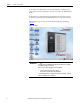
Chapter 4 Drive Terminal Application Overview The Drive Terminal for the PowerFlex 7000 Medium Voltage Drive is a software application which can be run on many Windows based systems. The communication to the PowerFlex 7000 drive is via Ethernet. The application is optimized using 640x480 screen resolution. Requirements The application will run on the following operating systems provided that the host hardware contains a minimum of .Net Framework 2.0 or .Net Compact Framework 2.0.
Chapter 4 Drive Terminal Application Depending on the hardware on which this application is running, the tab may be selected via a mouse click, or by touching the tab if using a touch sensitive screen. Navigating the Terminal Each screen is made up of four distinct areas as shown in Figure 24. Windows Title Provides the name of the drive to which the application is currently attached. This name is read from the drive and can be modified. Refer to the section Home Setup.
Drive Terminal Application Chapter 4 Soft Keypad Use the Soft keypad to enter data on a touch screen (Figure 25). Figure 25 - Soft Keypad The Soft Keypad is available on various dialogs and screens by pressing the symbol shown in Figure 26. Figure 26 - Soft Keypad Icon TIP The Terminal application is written to make use of a touch screen style of interface. On a touch screen, it is difficult to perform a double-tap, analogous to a mouse double-click, with any degree of accuracy or repeatability.
Chapter 4 Drive Terminal Application Common Panel The Common Panel (Figure 27) appears on a number of screens. It provides the same functionality regardless of the screen with which it is associated. Figure 27 - Common Panel The Common Panel: • Filters Parameters: The drive can contain a large number of parameters. In order to help reduce the number of parameters to select from or that are displayed, two types of filters can be applied.
Drive Terminal Application Chapter 4 3. Enter the PIN (password) for the given level. The PIN can be entered directly in the ‘Password’ input box or via the Soft Keypad. If the correct PIN is entered, the “Current Access” will change to the Access level requested. 4. Press OK. TIP Pressing the Logout push button will return the access level to the default Access level at which no parameters can be modified.
Chapter 4 Drive Terminal Application Search for Parameter There are two methods to search for a parameter, the parameter number or partial name. Search Parameters using Linear Number 1. Enter the parameter number in the Linear # field (Figure 30). The associated parameter appears in the list. 2. Click Select. Figure 30 - Search Dialog A parameter can be searched for using a couple of methods. Search Parameters using Partial Name 1. Type the parameter in the Partial Name field and press Enter.
Drive Terminal Application Home Chapter 4 The initial screen displayed when the terminal starts is the Home Screen. This screen (Figure 24) displays general information about the drive. • The drive name, which can be changed in the Setup Screen. • Four analog style meters. The default meters show Speed, Current, Voltage and Power. The meters can be changed to other parameters within the drive via the Setup Screen. • The status of the drive. • A Hobbs style meter giving the running hours of the drive.
Chapter 4 Display Drive Terminal Application The display screen, shown in Figure 31, is used to both monitor and make changes to any parameter in the drive. Figure 31 - Display Screen The screen is arranged into two panes. The left pane shows the name of the groups within the selected file, while the right pane shows the parameters which are within the selected group. The contents of the two panes are filtered according to current Access Level and the Read/Write filter (see Common Panel on page 32).
Drive Terminal Application Chapter 4 The column headers of the right pane are “Parameter Name”, “Value” and “Units”. Clicking on the Value header displays a dialog which provides additional information for the selected parameter as well as modification of the parameter.
Chapter 4 Drive Terminal Application Binary Parameter The dialog used for a binary type of parameter, typical of Figure 33, shows a descriptive string for each bit position within the parameter. The ‘A’ column shows the actual state of the bit. The ‘N’ column shows the new value that has not yet been applied. To change the state of a bit: • Click the ‘N’ check box for the appropriate bit. TIP To quickly clear all bits, click Reset All. To set all bits, click Set All.
Drive Terminal Application Chapter 4 To change the value of the parameter: 1. Select the New Value pulldown menu. 2. Select the new value which will be displayed in the ‘New Value’ field. The Default button selects the default value for the ‘New Value’ field. 3. Press the ‘Apply’ or ‘OK’ button. To leave the dialog without applying the new value, press Cancel.
Chapter 4 Alarms Drive Terminal Application In the PowerFlex 7000, “Alarms” refer collectively to ‘Faults’ and ‘Warnings’. The Alarms screen, typical of Figure 36, provides two tabs to independently show the Warnings or the Faults. TIP The Alarm Screen Common Panel shows a timestamp for the last time the drive was started and stopped for any reason. Figure 36 - Alarm Screen Select the desired queue by selecting the tab. The operation of both queues is identical.
Drive Terminal Application Chapter 4 Alarm Help Additional information about the alarm is available by selecting the alarm and pressing Alarm Help. A dialog typical of Figure 37, will be displayed. Figure 37 - Alarm Help Clearing Alarm Queue The ‘Clear Queue’ button clears the currently selected alarm queue. This operation may only be performed if the Access level is Basic or greater. The ‘Reset Drive’ button resets the drive but does not reset the queue.
Chapter 4 Setup Drive Terminal Application The Setup group of screens, typical of Figure 38, modifies the same drive parameters as the Display screen, but in a task oriented, context-friendly format. It is intended that this screen will be used for drive commissioning.
Drive Terminal Application Chapter 4 Assign a Parameter Numerous Setup screens require the user to select and assign a parameter to a function using the same method. 1. Select the desired function from the first column. 2. Press the ‘Parameter’ column heading to open the Select Parameter dialog (Figure 39). Figure 39 - Select Parameter TIP Alternatively, after selecting the associated function from the first column, the ‘Search’ button will find the parameter by Parameter number or by Name. 3.
Chapter 4 Drive Terminal Application Configure Analog Ports The Analog Setup screen, typical of Figure 40, shows all analog output ports of the drive to which a parameter can be assigned. Assign a Parameter to an Analog Output Port 1. Select the desired port from the Output column. 2. Press the Parameter column header. Alternatively, press the Search button (see Search for Parameter on page 34). Some of the analog outputs also contain a ‘Scaling’ parameter which is associated with the output.
Drive Terminal Application Chapter 4 Configure PLC Link The PLC Setup Screen (Figure 41) shows the parameter links which are assigned to PLC Input and PLC Output links. Toggle between ‘Inputs’ and ‘Outputs’ by pressing the respective button on the right side of the screen. Assign a Parameter to an Analog Output Port 1. Select the desired link from the left column (Figure 41). 2. Press the Parameter column header. Alternatively, press the Search button (see Search for Parameter on page 34).
Chapter 4 Drive Terminal Application Configure XIO The XIO configuration screen (Figure 42) provides two XIO functions. The left pane is used to assign functional group of I/O to a particular card number. The right pane is used to assign a selectable function to the outputs of the Standard I/O card. Figure 42 - XIO Configuration Setup Assign an XIO Card 1. Select the ‘Function’ from the list in the left panel. 2. Press the ‘Location’ column header to open an Enum Parameter dialog.
Drive Terminal Application Chapter 4 Enable or Disable Fault Masks The drive contains numerous fault masks which enable or disable whether that particular fault occurs. The screen typical of Figure 44 contains two panels. The left shows the faults which are enabled and the right panel shows the faults which are disabled. Clicking on the column headers sorts the list by either standard drive ordering or alphabetically. To change the status of a particular fault: 1.
Chapter 4 Drive Terminal Application Customize External Alarm Text The PowerFlex 7000 drive contains an XIO card which is used for customer defined alarms. A custom text string can be assigned to the inputs of this card via this setup screen, typical of Figure 45. Figure 45 - External Alarm Text Setup To change the assigned text: 1. Select the ‘Input’ to be changed in the left column. 2. Press the ‘Text’ column header (Figure 45). 3. Using a keyboard, enter the desired text. 4. Press Enter to exit.
Drive Terminal Application Chapter 4 Create a Custom Group of Parameters The custom setup (Figure 47) arranges user-definable groups. These groups are displayed wherever the normal File-Group-Parameter arrangement of predefined drive groups is displayed. These are typically found during a Select Parameter operation or on the Display screen. Since the custom group name could conflict with a predefined drive group, all custom groups are displayed in the color green in a list.
Chapter 4 Drive Terminal Application TIP The group assignments are stored locally on the terminal where this application is running. These defined groups will not be available on any other terminal, unless that terminal also defines the same groups. The custom group definitions are stored in a file called customdisplay_k1.xml which is typically in the ‘base’ directory. To change the name of an existing group: 1. Select a group from the Group Name column. 2. Press the Group Name column header. 3.
Drive Terminal Application Chapter 4 Home Setup The Home setup screen (Figure 49) changes the information found on the Home screen. From this screen, the name of the drive can be changed. The parameters assigned to the four meters on the screen can be modified along with the associated text for the meters. Figure 49 - Home Setup To change the drive name: 1. Click the data field associated with Drive Name. 2. Edit the name of the drive and press enter. To change the parameter associated with a meter: 1.
Chapter 4 Drive Terminal Application Diagnostics The PowerFlex 7000 drive can capture parameters on a real-time basis for later analysis. The Diagnostics screen, typical of Figure 50, consists of sub panels used to: • Configure the diagnostic setup • Control and provide status of the operation of the data collection. • View the collected data in tabular format • View the collected data in a plot Figure 50 - Diagnostics Screen Assign a Parameter to a Trace The data is captured to a number of traces.
Drive Terminal Application Chapter 4 To setup the parameter to appear in the plot: 1. Select the desired trace. 2. Press the Plot column header. The trace is removed from the plot in a similar manner. Diagnostic Trigger The trigger variable is always based on the first trace parameter. The trigger type is defined by the drive as either: • Single – the capture will only be triggered once and then must be manually armed again for an additional trigger.
Chapter 4 Drive Terminal Application Figure 51 - Binary Trigger Data Figure 52 - Enum Trigger Data Post Sample Value The Post Sample value can be set from 0...99%. To adjust the value: 1. Select the Post Sample field. 2. Press the Soft Keypad Icon and enter the desired value. Alternatively, a keyboard can be used to type directly into the field. 3. Press OK to accept. Rate Value The Rate of which the data is captured can be set from 0...20,000 mSec.
Drive Terminal Application TIP Chapter 4 The setup and trigger conditions are sent to the drive when the ‘Accept’ button is pressed or another screen is selected. This also arms the diagnostics trigger. Save and Retrieve Diagnostic Setups Any number of configured setups can be saved to any media accessible to the terminal. To save a configuration: 1. Press the Menu button. 2. Select Save. 3. Enter a filename and Press Save. To retrieve a stored setup: 1. Press the Menu button. 2. Select Load. 3.
Chapter 4 Drive Terminal Application Diagnostic Control The control screen, typical of Figure 53, shows the current status of the data capture and provides a means to control the data capture process. Last Trigger shows a time stamp (if available) when the last trigger occurred. The status of the data capture shows: • Stopped • Running • Triggered • Force Triggered When a trigger is stopped, it can be Re-Armed by pressing the ‘Re-Arm’ push button.
Drive Terminal Application Chapter 4 Diagnostics View Each trace is a column in the view window (Figure 54). Figure 54 - Diagnostics View Decode Binary Data The value can be decoded for data which is binary in nature. 1. Select the desired capture point (row). 2. Pressing the desired column header (Figure 54). 3. Select the desired condition to decode. 4. Press OK. The collection point at which the trigger condition occurred will be highlighted in RED.
Chapter 4 Drive Terminal Application Diagnostics Plot The plot screen (Figure 56) shows relationships and trends amongst the captured data. Figure 56 - Diagnostics Plot Trace parameters which were selected on the Diagnostics Setup screen are plotted automatically when the screen is selected. Add or Remove Parameters 1. Select the desired parameter. 2. Press the X column header to add or remove the parameter. 3. Press Update to redraw the new plot.
Drive Terminal Application Utility Chapter 4 The utility screen, typical of Figure 57, can: • Set the time and date within the drive • Show revision levels of all drive components • Transfer parameters between NVRAM and working RAM on the drive. • Transfer parameters between the drive and a file on any media accessible by this terminal. • Place the drive into Download mode for new firmware and modules. Figure 57 - Utility Screen Set Date and Time The current time and date is shown on the screen.
Chapter 4 Drive Terminal Application 2. To set the time, click on the hours:minute:seconds field and enter the desired value using a keyboard or the Soft Keypad Icon. To change the date, select the pulldown menu and select the new date using a keyboard or the Soft Keypad Icon. 3. Press Accept to change the value in the drive. Display Drive Revision Levels The center panel shows a tree view of all the modules within the drive and the associated revisions of each of the modules.
Drive Terminal Application Chapter 4 Place the Drive into Download Mode To load new firmware or other modules to the PowerFlex 7000 drive, it must first be placed into download mode. A minimum of “Advanced” access level is required to perform this operation. 1. Press Download (Figure 57). Figure 59 - Download Confirmation 2. Press OK to confirm the task. If the operation cannot be completed, the dialog in Figure 60 is displayed and the action will be aborted.
Chapter 4 Drive Terminal Application Control Panel The terminal can control the operation of the drive from a remote location. These functions mimic those which can be found on the drive door if supplied. The available functions are: • Stop • Start • Reset • Reverse • Reference Setpoint Indications of the drive status are: • Ready • Running • Faulted • Warning • Reverse • Frequency Reference The Control Panel is displayed by pressing the Status Bar on the bottom of any screen and is typical of Figure 62.
Drive Terminal Application Chapter 4 Configure Multiple Control Points The drive can be configured to allow more than one terminal device to be in control at a time. This is configured through parameter 981 (NetSrvr MPntCntl). To allow multiple control points: 1. Click Search in the Common Panel (Common Panel on page 32). 2. Enter 981 in the Linear # field and select the parameter from the list. 3. Select the desired configuration settings from the pulldown menu. 4. Click OK.
Chapter 4 Drive Terminal Application Configure Adapter Loss Parameter The Control Bar must actively communicate with the drive on a regular basis. If communication is interrupted between this terminal device and the drive prior to closing the Control Panel, the drive experiences an “Adapter Loss”. The action the drive takes on an Adapter Loss is determined by the configuration of the adapter.
Drive Terminal Application Communications Failure Chapter 4 When the terminal application cannot communicate to the drive, a communication error dialog appears (Figure 64). The error could be the result of a user action, such as putting the drive into download mode from another terminal, or cycling power to the drive. If this is the case, press Yes and the terminal will close.
Chapter 4 Drive Terminal Application Unable to Open Program A device is capable of running multiple terminal sessions, but only if they are to different drives. Any attempt to run more then one session on the same drive results in an error message (Figure 67). Figure 67 - Unable to Open Program If this occurs and no other terminal session is evident, the most likely cause is a previous session which did not close down properly due to some unknown error condition.
Chapter 5 Windows Explorer Overview This section demonstrates the use of Windows Explorer™ as it is available on every Windows based PC. However, other FTP clients however are equally usable. Chapter Objectives This chapter describes how the HMI Interface Board transfers files between the PC/Terminal and the PowerFlex 7000 Medium Voltage Drive. In this chapter, you will learn how to: • Copy and open files directly from the drive. • Use Windows Explorer to access the drive.
Chapter 5 Windows Explorer The directories and files can be opened or copied either individually or as a complete directory, the same as you would with any files contained on the hard drive of your PC/Terminal. The operating system uses a default program to open the files. EXAMPLE A .TXT file is, by default, opened by an ASCII viewer or editor. A .CSV file is opened by Excel™, if your PC knows this file type has been associated with the Excel program and the PC has Excel installed.
Windows Explorer Chapter 5 Copy or Restore Drive Parameters The parameters.csf file contains a copy of the drive parameters. To store this parameter set: • Copy this file and store in any desired location. To restore a parameter set: • Copy a previously saved .CSF file to this directory. The .CSF file is the same format as used by Drive Explorer, Drive Tools and other Rockwell Automation tools associated with the PowerFlex family of drives.
Chapter 5 Windows Explorer Configuration Tips Since the user can configure Windows Explorer in many ways, this section describes known setting requirements and issues seen with the use of Windows Explorer. • FTP clients must use PORT mode connections • Enable FTP Folder View This option is enabled by opening the Internet Explorer options, select the Advanced Tab and make sure the option is checked. • Windows Explorer opens two connections to the NetBurner module when it accesses a file.
Chapter 6 System Updates Overview The HMI Interface Board can be updated over a network. In doing so, only certain files and directories can be written to. These updates are completed using either an FTP Client such as Microsoft Windows Explorer or a supplied utility from Rockwell Automation. Chapter Objectives Using an FTP Client to Update Firmware This chapter describes how the HMI Interface Board updates files and firmware in the PowerFlex 7000 Medium Voltage Drive.
Chapter 6 System Updates Forge Package Updater The Package Updater utility is a program which updates the drive and operates on both Windows and Windows CE platforms. It is supplied by Rockwell Automation. It can be provided as a separate .PKG file, or can be embedded within this utility. Figure 73 - Package Updater Update the HMI Interface Board 1. Open the Package Updater utility (Figure 73). Refer to the Windows Explorer section under Drive Menu on page 24. 2.
System Updates Chapter 6 4. Click Yes, and enter the appropriate PIN value for the desired access level. TIP The PIN codes required for the firmware download are the same PIN codes used in the operator interface. Unless changed, the Advanced PIN is 0 by default. If an incorrect PIN is entered, the update process must be restarted. 5. Press Enter on the keyboard. A bar graph shows the progress of the file transfer to the HMI Interface Board.
Chapter 6 System Updates TIP The package contents of the either selected option can be previewed by pressing the Package. The Package dialog (Figure 74) shows the contents of the SD Card which will be created or updated on the HMI Interface Board module. Drive Firmware and HMI Interface Board Firmware is also included in the package if so stated. In the provided example, the HMI Interface Board Firmware will be updated, but no update is contained for the Drive Firmware.
Chapter 7 PanelView Plus 6 Terminal Overview The standard local and remote terminal options for the PowerFlex 7000 Medium Voltage Drive is the Rockwell Automation PanelView Plus 6 Terminal. This terminal utilizes the Windows CE6 Operating System. IMPORTANT Chapter Objectives If the PowerFlex 7000 Medium Voltage Drive already contains a PanelView Plus terminal, the setup described in this section will have already been completed.
Chapter 7 PanelView Plus 6 Terminal Access to the Desktop All terminals are initially shipped with desktop access disabled. To use the terminal with the PowerFlex 7000 Medium Voltage Drive, the Desktop must be accessible. To access the desktop: 1. Select ‘Terminal Settings’ – F4. 2. Select ‘Desktop Access Setup’ and press Enter. 3. Set the ‘Desktop Access’ – F2 to ‘Allow’. The required default password is “password”, (case sensitive).
PanelView Plus 6 Terminal Chapter 7 3. Click PCI-KS88411 (note the name could be different). If you are required to use a static IP Address, then set the radio button to Specify an IP Address (Figure 76). Figure 76 - IP Address Settings The specific IP Address, Subnet Mask and Default Gateway that you use will depend on your network. Consult with your network administrator.
Chapter 7 PanelView Plus 6 Terminal 3. Select Patch PV CE6 from the list. Figure 77 - HMI Interface Board Webpage 4. Select Run this Program from its current location and press OK. After the download, the program “Patch PanelView Terminal OS Utility” is displayed. 5. Press OK. 6. Press Close when the program has completed. The terminal is now ready to be used with the PowerFlex 7000 Medium Voltage Drive.
PanelView Plus 6 Terminal File Transfer Client Chapter 7 An FTP client has been written specifically for use by the CE Terminal and is obtainable from the PowerFlex 7000 Medium Voltage Drive HMI Interface Board. To Transfer a File or directory using an FTP Client 1. Select the appropriate application from the Forge Shell toolbox (see Drive Menu on page 24). The left pane is the directory structure of the storage device(s) in the terminal. The right pane is the directory structure of the drive. 2.
Chapter 7 PanelView Plus 6 Terminal Notes: 80 Rockwell Automation Publication 7000-UM201B-EN-P - June 2013
Appendix A Hardware Introduction The HMI Interface Board module (Figure 79) consists of two circuit boards sandwiched together. The base board is the PFNI (PowerFlex Network Interface Board). It contains a socket into which the processor module (NetBurner) connects into. This assembly is collectively referred to as the HMI Interface Board. The HMI Interface Board (Part no. 80190-780-01-R) connects into the DPM (Drive Processor Module) and becomes part of the drive control platform.
Appendix A Hardware Unless directed by Rockwell Automation, this switch will always be in the Default position. Switch 2: Internal DIM On Internal DIM disabled Off Internal DIM enabled Default Off The PFNI has a built in DIM as well as a socket for an external DIM. When the external DIM is plugged in, it is always active, regardless of this switch setting. When the internal DIM is in use, this switch allows for the rare occasion that it must be disabled.
Hardware Appendix A Ethernet Port The standard RJ45 connector for Ethernet. The port is configured for 100 Mbps, Full Duplex. A standard Cat5 Ethernet cable is used for connection. DIM (Drive Identity Module) Socket The HMI Interface Board module plugs into the DPM via the existing DIM socket on the DPM. To accommodate the existing external DIMs, the DIM can be reinserted into the socket on the PFNI board.
Appendix A Hardware Network Protocols The HMI Interface Board module is an Ethernet device. The network must allow certain ports to be accessed on PCs or Terminals which interact with the HMI Interface Board. IMPORTANT Security of a Network is the responsibility of the IT Department which maintains the network in the Application of the device. The HMI Interface Board does not provide any form of firewall protection.
Glossary Base Discovery The directory where .XML files are stored by default. When the application is launched from a remote device, a directory named “Temporary Internet Files’ will be created on the local terminal. Within this directory, will be subdirectories which are named according to the IP address of the remote device. This subdirectory which corresponds to the IP address is the Base Directory.
Glossary Notes: 86 Rockwell Automation Publication 7000-UM201B-EN-P - June 2013
Rockwell Automation Support Rockwell Automation provides technical information on the Web to assist you in using its products. At http://www.rockwellautomation.com/support, you can find technical manuals, technical and application notes, sample code and links to software service packs, and a MySupport feature that you can customize to make the best use of these tools. You can also visit our Knowledgebase at http://www.rockwellautomation.