
Instruction Manual

1 Publication 700-UM002B-EN-D - June 2010
Chapter
2
Product Features
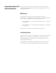
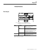
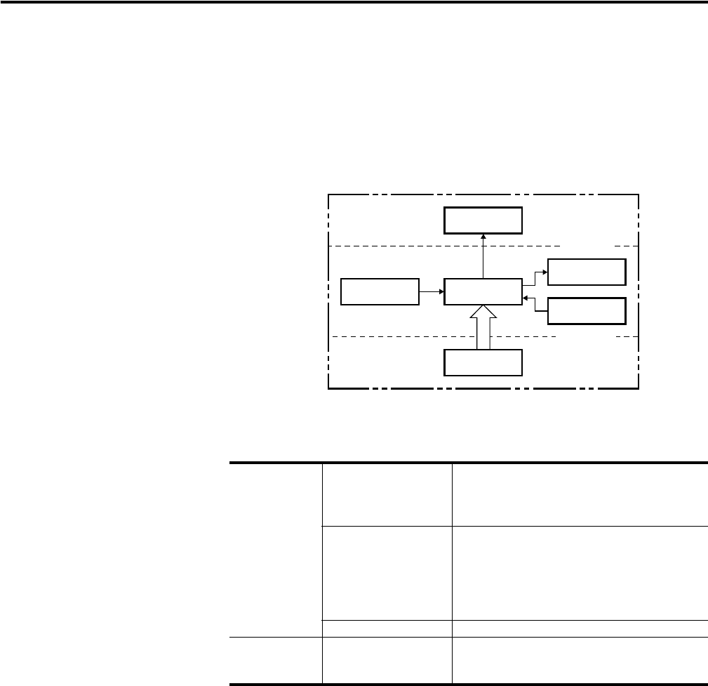
Block diagram
Note: 700-HX86SA17: Basic insulation is provided
700-HX86SU24: Basic insulation is not provided
➊
Gate capability not available.
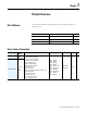
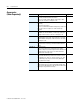
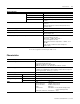
Inputs Start signal Stops timing in A-2 and A-3 (power ON delay)
modes.
Starts and stops timing in S mode.
Start timing in other modes.
Reset Resets present value. (In elapsed time mode, the
present value returns to 0; in remaining time
mode, the present value returns to the set value.)
Count inputs are not accepted and control output
turns OFF while reset input is ON.
Reset indicator is lit while reset input is ON.
Gate ➊ Inhibits timer operation.
Outputs Control output (OUT) Outputs take place according to designated
operating mode when timer reaches
corresponding set value.
Input circuit
Internal control
circuit
Power supply
circuit
(Basic
insulation)
Display circuit
Key switch
circuit
(See note.)
Output circuit