Multifunction Digital Timer 700-HX User Manual
Important User Information Because of the variety of uses for the products described in this publication, those responsible for the application and use of this control equipment must satisfy themselves that all necessary steps have been taken to assure that each application and use meets all performance and safety requirements, including any applicable laws, regulations, codes and standards.
European Communities (EC) Directive Compliance If this product has the CE mark it is approved for installation within the European Union and EEA regions. It has been designed and tested to meet the following directives.
Preface Manual Objectives The purpose of this manual is to provide you with the additional information necessary to apply the 700-HX Multifunction Digital Timer. Described in this manual are methods for applying and troubleshooting this product. Who Should Use This Manual This manual is intended for qualified personnel responsible for setting up and servicing these devices.
Preface 2 Publication 700-UM002B-EN-D - June 2010
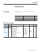
Chapter 1 Product Overview Bill of Material Your 700-HX Multifunction Digital Timer product package includes the following items: Item No. Description Quantity 700-HX Digital Timing Relay 1 — 6-Language Instruction Sheet 1 — Rubber Gasket 1 Basic Product Information Cat. No.
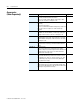
1-2 Product Overview Accessories (Order Separately) Cat. No. 700-HN100 700-HN125 199-DR1 700-HN108 700-HN130 700-HN132 700-N40 700-N41 Publication 700-UM002B-EN-D - June 2010 Description Screw Terminal Tube Base Sockets — Panel or DIN Rail Mounting Guarded Terminal Construction 8-pin for use with Bulletin 700-HX timing relays. Order must be for 10 sockets or multiples of 10.
Chapter 2 Product Features Block diagram Output circuit (Basic insulation) Display circuit Input circuit Internal control circuit Key switch circuit (See note.) Power supply circuit Note: 700-HX86SA17: Basic insulation is provided 700-HX86SU24: Basic insulation is not provided Inputs Start signal Reset Outputs Gate ➊ Control output (OUT) Stops timing in A-2 and A-3 (power ON delay) modes. Starts and stops timing in S mode. Start timing in other modes. Resets present value.
2-2 Product Features Switching operations ( 104) Engineering Data (Reference Values) Reference:A maximum current of 0.15 A can be switched at 125V DC (cosφ=1) and a maximum current of 0.1 A can be switched if L/R is 7 ms. In both cases, a life of 100,000 operations can be expected. The minimum applicable load is 10 mA at 5V DC (failure level: P). 1,000 500 100 30V DC L/R=7 ms 50 250V DC/30V cos =1 10 250V AC cos =0.
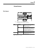
Product Features Electrical Ratings Inputs Input signals Input method Start, reset Power reset Control output External Power Supply Key Protect Memory backup Accuracy of Operating Time and Setting Error ➊ 2-3 Start, reset No-voltage input via:NPN transistor or switching of contact Minimum input signal width: 1 or 20 ms (selectable) Minimum power-opening time: 0.
2-4 Product Features Approved standards UL508, CSA C22.2 No.14 Conforms to EN 61812-1 (Pollution degree 2/overvoltage category III) Conforms to VDE0106/P 100 (Finger Protection), conforms to NEMA output rating (N/F) Panel surface:IP66 and NEMA Type 4X (indoors) ➊ Approx. 100 g Enclosure ratings Weight ➊An attached waterproof packing is necessary to ensure IP66 waterproofing between the 700-HX and installation pan. Nomenclature Operation Key Display Section 1. Key Protect Indicator (orange) 2.
Chapter 3 Functions Settings For Advanced Functions Power ON Run mode For details on operations in run mode, refer to 3-10. Note: See note 1. 3 s min. See note 2. 3 s min. 1. If the mode is switched to the function setting mode during operation, operation will continue. 2. Changes made to settings in function setting mode are enabled for the first time when the mode is changed to run mode. Also, when settings are changed, the timer is reset (time initialized and output turned OFF).
3-2 Functions Explanations of Functions Time Range (timr) Set the range to be timed in the range 0.000 s… 9,999 h. Use the operation keys if these settings are required. Timer Mode (timm ) Set either the elapsed time (UP) or remaining time (DOWN) mode. Output Mode (outm) Set the output mode. The possible settings are A, A-1, A-2, A-3, B, B-1, D, E, F, Z and S. (For details on output mode operation, refer to “Timing Charts” on page 3-11.
Functions 3-3 Key Protect Level (kypt) When the key-protect switch in set to ON, it is possible to prevent setting errors by prohibiting the use of certain operation keys by specifying the key protect level (KP-1 to KP-7). The key protect indicator is lit while the key-protect switch is set to ON. Confirm the ON/OFF status of the key-protect switch after the 700-HX is mounted to the panel.
3-4 Functions Operation in Run Mode When Output Mode Is Not Z Present value Set each digit for the set value using the corresponding keys. Set value When Output Mode Z Is Selected Present value Set each digit for the ON duty ratio using the corresponding (The keys for the 4th digit cannot be used.) keys. ON duty ratio Present value Set each digit for the cycle time using the corresponding keys. Cycle time Present Value and Set Value These items are displayed when the power is turned ON.
Functions 3-5 Elapsed cycle time ON duty set as a percentage Up/down keys used for analog adjustment of the ON duty Cycle time Close Open ON duty (%) Output control Opening/closing valve ON duty Operation (Repeat Cycle Function) Fully closed↔Fully open 0%↔100% Switching from Timer to Repeat Cycle The 700-HX is factory-set for timer operation. To switch to repeat cycle operation, use the procedure given below. For details, refer to page Appendix-2.
3-6 Functions Settings for Advanced Functions . Power ON 3 s min. Run mode *1 Function setting mode 3 s min. *2 *1. If the mode is switched to the function setting mode during operation, operation will continue. *2. Changes made to settings in function setting mode are enabled for the first time when the mode is changed to run mode. Also, when settings are changed, the timer is reset (time initialized and output turned OFF). OFF time range Set the OFF time range using the keys.
Functions From previous page 3-7 To previous page Function setting mode Set value upper limit 1 Set value upper limit 2 Set the digits for the set value limit using the corresponding 1 9999 (1) (9999) Set the digits for the set value limit using the corresponding 1 9999 (1) (9999) Set the key protect level using the keys. keys. keys.
3-8 Functions Explanation of Functions (Repeat Cycle Function) OFF Time Range (oftr) Set the time range for the OFF time in the range 0.000 s… 9,999 h. Use the operation keys if another type of setting is required. ON Time Range (ontr) Set the time range for the ON time in the range 0.000 s …9,999 h. Use the operation keys if another type of setting is required. Timer Mode (timm) Set either UP (incremental) or DOWN (decremental) timer mode.
Functions (See note) OFF 3-9 ON Note: Factory-set to OFF Key protect indicator Level KP-1 (default setting) KP-2 KP-3 KP-4 KP-5 KP-6 KP-7 Meaning Prohibits changing the mode to timer/repeat cycle selection mode or function setting mode. The 700-HX can only be used in run mode. Prohibits changing the mode to timer/repeat cycle selection mode or function setting mode. The 700-HX can only be used in run mode. Also prohibits use of the reset key.
3-10 Functions Operation in Run Mode Present value Set the digits for the OFF set time using the corresponding keys. OFF set time Present value Set the digits for the ON set time using the corresponding keys. ON set time Present Value and OFF Set Time The present value is displayed in the main display and the OFF set time is displayed in the sub-display. “SET1” lights at the same time.
Functions 3-11 Run Mode Power ON + To change the mode to timer/ repeat cycle selection mode, hold 1 key for 1 s min. with the MODE key held down. down the The MODE key must be pressed before the 1 key. If the 1 key is pressed first, the mode will not change. 1 Timer/ Repeat cycle Selection Mode 1 s min. Select either timer operation or repeat cycle operation. using the keys. Timer/Repeat m cycle operation MODE Note: The 700-HX is factory-set for timer operation. Note: 1.
3-12 Functions Output Mode A-1: Signal ON-Delay 2 (Timer resets when power comes ON.) Power Timing starts when the start signal goes ON, and is reset when the start signal goes OFF. While the start signal is ON, the timer starts when the power comes ON or when the reset input goes OFF. The control output is controlled using a sustained or one-shot time period.
Functions 3-13 Output mode B: Repeat Cycle 1 (Timer resets when power comes ON.) One-shot Output Timing starts when the start signal goes ON. The control output is turned ON when time is up. While the start signal is ON, the timer starts when the power comes ON or when the reset input goes OFF.
3-14 Functions Output mode D: Signal OFF-delay (Timer resets when power comes ON.) The control output is ON when the start signal is ON (except when the power is OFF or the reset is ON). The timer is reset when the time is up. Power Start signal Basic Operation Gate Power Reset ** Start signal input Control output Set value UP Timing diagram 0 Set value DOWN 0 Timing Output * Output functions only during start signal input when setting is 0. ** Start signal input is enabled during timing.
Functions 3-15 Z mode: ON/OFF-duty Adjustable Repeat Cycle Power Start signal Gate Timing starts when the start signal goes ON. The status of the control output is reversed when time is up (ON at start). While the start signal is ON, the timer starts when power comes ON or when the reset input goes OFF.
3-16 Functions Repeat Cycle Operation Output mode TOFF: Flicker OFF start 1 (Timer resets when power comes ON) Timing starts when the start signal goes ON. The status of the control output is reversed when time is up (OFF at start). While the start signal is ON, the timer starts when the power comes ON or when the reset input goes OFF.
Functions 3-17 Timing starts when the start signal goes ON. The status of the control output is reversed when time is up (OFF at start). While the start signal is ON, the timer starts when the power comes ON or when the reset input goes OFF. Power Start signal Basic Operation Gate Power Reset * Start signal input OFF time UP ON time Timing OFF Timing ON Timing OFF a b Output (a + b = ON time) * Start signal input is disabled during timing.
3-18 Functions Publication 700-UM002B-EN-D - June 2010
Chapter 4 Dimensions 700-HX Flush Mounting/ Socket Mounting Note: All units are in millimeters unless otherwise noted. 48×48 7.5 63.7 14.3 44.8×44.
4-2 Dimensions Panel Cutouts Panel cutouts are as shown below (according to DIN43700). 60 min. 45 +0.6 −0 45 +0.6 −0 60 min. 15 min. Note: 1. The mounting panel thickness should be 1…5 mm. 2. To allow easier operability, it is recommended that adapters are mounted so that the gap between sides with hooks is at least 15 mm. 3. It is possible to mount timers side by side, but only in the direction without the hooks. n side by side mounting A +1 A = (48n - 2.5)0 With 700-HN132 attached: A = (51n - 5.
Chapter 5 Installation Terminal Arrangement 700-HX Internal circuit Signal Reset 4 5 3 6 7 2 1 8 0V ϑҥϒ (–) ϑҤϒ (+) Note: Do not connect unused terminals as relay terminals.
5-2 Installation Input Connections The input of the 700-HX is no-voltage input only.
Installation 5-3 Applicable Two-wire Sensor Leakage current: 1.5 mA max. Switching capacity: 5 mA minimum Residual voltage: 3V DC max.
5-4 Installation Publication 700-UM002B-EN-D - June 2010
Chapter 7 Precautions ATTENTION ! ATTENTION ! ATTENTION ! ATTENTION ! 1 Do not use the product in locations subject to flammable or explosive gases. Doing so may result in explosion. The service life of the output relays depends on the switching capacity and switching conditions. Consider the actual application conditions and use the product within the rated load and electrical service life. Using the product beyond its service life may result in contact deposition or burning.
7-2 Precautions Power Supplies Make sure that the voltage is applied within the specified range, otherwise the internal elements of the Timer may be damaged. When turning the power ON and OFF, input signal reception is possible, unstable, or impossible as shown in the diagram below.
Precautions Self-diagnostic Function 7-3 The following displays will appear if an error occurs. Confirm the error type using the display, and take the appropriate countermeasures. Main display Sub- display No e1 display No display e2 e2 sum No Change e3 ➋ Error CPU Memory (RAM) Memory (EEP) ➊ Output ON count alarm set value exceeded Correction Either press the reset key or reset the power supply. Reset the power supply. If normal operation is still not restored, replacement or repair is necesary.
7-4 Precautions Operating mode A-3, b-1, F, toff-1/ ton-1 mode Other mode Overwriting timing When power is turned OFF. When settings are changed. Wiring Wiring input lines in the same conduit as power lines or other high-voltage lines may result in malfunction due to noise. Wire the input lines separately, away from lines carrying high-voltages. In addition, make the input wiring as short as possible and use shield lines or metal wiring conduits.
Precautions • • • • • 7-5 Organic solvents (such as paint thinner), as well as very acidic or basic solutions might damage the outer casing of the timer. Use the product within the ratings specified for temperature and humidity. Do not use the product in locations where condensation may occur due to high humidity or where temperature changes are severe. Store at the specified temperature.
7-6 Precautions Publication 700-UM002B-EN-D - June 2010
Appendix Using the Operation Keys Timer Operation Operation stopped Can be in operation Power ON Timer/Repeat Cycle selection mode + 1 + 1 1 s min. Run mode 3 s min. Timer (Except for Z mode) 3 s min. Timer/Repeat Cycle selection 1 s min.
Appendix-2 List of Settings Fill in your set values in the set value column of the following tables for quick reference. Timer/Repeat Cycle Selection Mode Parameter Parameter Setting range name func tim/twin Timer/ Repeat Cycle selection Dafault value Unit tim --- Set value Settings for Timer Operation Run Mode when Output Mode is Not Z Parameter name Present Set value value, set value Present value Publication 700-UM002B-EN-D - June 2010 Parameter Setting range 0.00 … 99.
Appendix-3 Run Mode when Output Mode = Z Parameter name Present Cycle value, time cycle time Parameter Setting range Dafault Unit value 0.00 s 0.00 …99.99 (Time range: --,--s) 0.0 … 999.9 0.0 (Time range: ---,-s) 0 … 9999 (Time range: ----s) 0 Present value Present ON value, duty ratio ON duty Present ratio value Set value s 0:00 … 99:59 (Time range: --min--s) 0.0 … 999.9 (Time range: ---,-min) 0 … 9999 (Time range: ----min) 0:00 … 99:59 (Time range: --h--min) 0.0 … 999.
Appendix-4 Settings for Repeat Cycle Operation Run Mode Parameter name Parameter Setting range 0.00 …99.99 (Time range: --,--s) 0.0 … 999.9 (Time range: ---,-s) 0 … 9999 (Time range: ----s) 0:00 … 99:59 (Time range: --min--s) 0.0 … 999.9 (Time range: ---,-min) 0 … 9999 (Time range: ----min) 0:00 … 99:59 (Time range: --h--min) 0.0 … 999.9 (Time range: ---,-h) 0 … 9999 (Time range: ----h) 0.000 … 9.
Appendix-5 Publication 700-UM002B-EN-D - June 2010
Allen-Bradley is a registered trademark of Rockwell Automation Publication 700-UM002B-EN-D - June 2010 1 © 2010 Rockwell Automation, Inc. All Rights Reserved. Printed in the U.S.A.