" $ $ # #$"% $ % # #% $ $ ' $ %$ $
Table of Contents 1.0 Introduction . . . . . . . . . . . . . . . . . . . . . . . . . . . . . . . . . . . . . . . . . . . . . . . 1Ć1 2.0 Mechanical/Electrical Description . . . . . . . . . . . . . . . . . . . . . . . . . . . 2Ć1 2.1 Mechanical Description . . . . . . . . . . . . . . . . . . . . . . . . . . . . . . . . . . . 2Ć1 2.2 Electrical Description . . . . . . . . . . . . . . . . . . . . . . . . . . . . . . . . . . . . . 2Ć1 3.0 Installation . . . . . . . . . . . . . . . . . . . . . . . . . . . .
! # " # ! # ! ! # ! " !
! ! ! ! ! ! ! !
fafadfdfdasfdsfdsdsdfdsfdsfdsfsdfdsa afdfdsfdsfdfdsfdsfsadfda asfdfaddfdd
The products described in this instruction manual are manufactured or distributed by Reliance Electric Company or its subsidiaries. The 24V AC/DC Input module accepts up to a maximum of sixteen 24 volt control signals as inputs to DCS 5000, AutoMax, and AutoMate systems. The input signals may be 50 or 60 hertz AC or DC. Inputs have 2500 volt isolation to logic common. The module contains four isolated commons, each having four inputs.
fafadfdfdasfdsfdsdsdfdsfdsfdsfsdfdsa afdfdsfdsfdfdsfdsfsadfda asfdfaddfdd
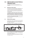
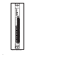
2.0 MECHANICAL/ELECTRICAL DESCRIPTION The following is a description of the faceplate LEDs, field termination connectors, and electrical characteristics of the field connections. 2.1 Mechanical Description The input module is a printed circuit board assembly that plugs into the backplane of the DCS 5000/AutoMax or AutoMate rack. It consists of a printed circuit board, a faceplate, and a protective enclosure. The faceplate contains tabs at the top and bottom to simplify removing the module from the rack.
24V AC/DC INPUT 61C516 0 1 2 3 4 5 6 7 8 9 10 11 12 13 14 15 C B 0 1 1 2 2 3 3 4 C1 5 4 6 5 7 6 8 7 9 C2 1 0 8 1 1 9 1 2 10 1 3 11 1 4 C3 1 5 12 1 6 13 1 7 14 1 8 15 1 9 C4 2 0 3 2 D E 1 F G 6 7 8 Figure 2.
This section describes how to install and remove the module and its cable assembly. The installation of wiring should conform to all applicable codes. To reduce the possibility of electrical noise interfering with the proper operation of the control system, exercise care when installing the wiring from the system to the external devices. For detailed recommendations refer to IEEE 518. Use the following procedure to install the module: Step 1.
AC LINE FU 24V AC TB AUX STOP 1 2 START 3 1 LS 4 5 Figure 3.1 Ć Typical Field Signal Connections for 24V AC Inputs Step 4. Take the module out of its shipping container. Take it out of the antiĆstatic bag, being careful not to touch the connectors on the back of the module. Step 5. Insert the module into the desired slot in the rack. Use a screwdriver to secure the module into the slot. Step 6.
At the time of installation, rotate the keys on the module and the connector so that they can be connected together securely. It is recommended that, for modules so equipped, the keys on each successive module in the rack be rotated one position to the right of the keys on the preceding module. If you use this method, the keys on each connector will be positioned in such a way as to fit together only with a specific module, and there will be little chance of the wrong connector being attached to a module.
fafadfdfdasfdsfdsdsdfdsfdsfdsfsdfdsa afdfdsfdsfdfdsfdsfsadfda asfdfaddfdd
4.0 PROGRAMMING This section describes how data is organized in the module and provides examples of how the module is accessed by the application software. For more detailed information, refer to the AutoMax Enhanced BASIC Programming instruction manual (JĆ3675) for DCS 5000/AutoMax systems or the AutoMate 30/40 Software Reference instruction manual (JĆ3150) for AutoMate systems. 4.1 Register Organization The data in the module is organized as one 16 bit register.
4.2.2 Reading Data In Application Tasks For an input module to be referenced by application software, you must assign symbolic names to the physical hardware. Each application program that references the symbolic names assigned to the input module in the configuration must declare those names COMMON (or global in ladder programs created using version 4.0 or later of the AutoMax Programming Executive).
4.2.2.3 Control Block Task Example 2400 2500 3000 5000 5500 6000 COMMON STARTPB@ \!Start pushĆbutton LOCAL MOMENTARY@ \!Momentary output ! CALL TRANSITION( INPUT=STARTPB@, OUTPUT=MOMENTARY@) ! END The symbolic name STARTPB@ references the input module. The symbolic name MOMENTARY@ is local to the control block task and does not have I/O associated with it. Refer to the Control Block Language Instruction Manual (JĆ3676) for more information. 4.2.
4.3.1 Ladder Diagram Example The following sample MOVMR instruction block is used to access a 24V AC/DC input module located in slot 4 of an AutoMate rack that contains an AutoMate 30 Processor. The data from the module will be stored in register 2000. EN EN MOVMR LENGTH: 1 ADDRS: 400000 40 .00 76 .00 I/O-M: M B,H,W,S: S DEST: 2000 VALUE: Note that the coil address shown in the example is not valid for an AutoMate 40 Processor. 4.3.
5.0 DIAGNOSTICS AND TROUBLESHOOTING This section explains how to troubleshoot the module and field connections. 5.1 Incorrect Data Problem: The data is either always off, always on, or different than expected. The possible causes of this are a module in the wrong slot, a programming error, or a malfunctioning module. It is also possible that the input is either not wired or wired to the wrong device. Use the following procedure to isolate the problem: Step 1.
indirectly by monitoring the name with the VARIABLE MONITOR function in the ReSource Software. For both DCS 5000/AutoMax systems and AutoMate systems, verify that the program reading the module is executing fast enough to catch all of the input changes. Step 5. Verify that the hardware is working correctly. Toggle the input device. Verify that the LED associated with the particular bit is also toggling. If it is not, the input circuit on the module is malfunctioning.
Problem: A 31" or 50" through 58" appears on the Processor module's LED in DCS 5000/AutoMax systems. In AutoMate systems, a 1" appears in any bit location of register 3764 of an AutoMate 30 or register 17564 of an AutoMate 40. This error message indicates that there was a bus error when the system attempted to access the module. The possible causes of this error are a missing module, a module in the wrong slot, or a malfunctioning module.
fafadfdfdasfdsfdsdsdfdsfdsfdsfsdfdsa afdfdsfdsfdfdsfdsfsadfda asfdfaddfdd
Appendix A Technical Specifications Ambient Conditions Storage temperature: -40oC Ć 85oC Operating temperature: 0oC Ć 60oC Humidity: 5Ć90% nonĆcondensing Maximum Module Power Dissipation Watts: 7 Dimensions Height: 11.75 inches Width: 1.25 inches Depth: 7.375 inches System Power Requirements +5 volts: 1A Input Circuit Number of inputs: 16 Maximum operating voltage: 30 volts rms Minimum turnon voltage: 20.
fafadfdfdasfdsfdsdsdfdsfdsfdsfsdfdsa afdfdsfdsfdfdsfdsfsadfda asfdfaddfdd
Appendix B Module Block Diagram 24V AC/DC INPUT MODULE 61C516 ADDRESS ID BUS BUS ADDRESS ADDRESS DECODER BUS 0 1 2 3 C1 FILT ISOL FILT ISOL FILT ISOL FILT ISOL 6 7 C2 FILT ISOL FILT ISOL FILT ISOL FILT ISOL FILT ISOL FILT ISOL FILT ISOL FILT ISOL 8 9 10 11 C3 14 15 C4 READ MEM 2 3 CONTROL LOGIC BYTE HI EN 4 5 6 7 8 9 10 11 BIT 0 1 2 3 4 5 6 7 8 9 10 11 12 13 14 15 OUTPUT DATA BUFFER DATA BUS BUS +5V 12 13 1 XFER ACK 4 5 0 FILT ISOL FILT ISOL FILT ISOL FILT
fafadfdfdasfdsfdsdsdfdsfdsfdsfsdfdsa afdfdsfdsfdfdsfdsfsadfda asfdfaddfdd
fafadfdfdasfdsfdsdsdfdsfdsfdsfsdfdsa afdfdsfdsfdfdsfdsfsadfda asfdfaddfdd
& ! #! "" % " "" % " "#" &"#% # ! "#! # # ! # " $" # # " " # # # # $# $ &
61C505 Ć DINĆStyle Terminal Strip/Cable Assembly (Fused) This assembly consists of a DINĆstyle terminal strip with fuses, cable, and mating connector. It is used to connect field signals to the faceplate of the input module.
61C506 Ć DINĆStyle Terminal Strip/Cable Assembly (Unfused) This assembly consists of a DINĆstyle terminal strip, cable, and mating connector. It is used to connect field signals to the faceplate of the input module.
fafadfdfdasfdsfdsdsdfdsfdsfdsfsdfdsa afdfdsfdsfdfdsfdsfsadfda asfdfaddfdd
Appendix E Defining Variables in the Configuration Task Local I/O Definition This section describes how to configure the input module when it is located in the same rack (i.e., the local rack) as the Processor module that is referencing it. Refer to the figure below. Note that this procedure is used only if you are using the AutoMax Programming Executive software Version 2.1 or earlier.
Use the following method to reference individual inputs on the module. A maximum of 16 statements can be included in the configuration task (one for each bit). The symbolic name of each bit should be as meaningful as possible: nnnnn IODEF SYMBOLIC_NAME@[ SLOT=s, REGISTER=0, BIT=b] where: nnnnn Ć BASIC statement number. This number may range from 1Ć32767. SYMBOLIC_NAME% Ć A symbolic name chosen by the user and ending with (%).
Use the following method to reference all 16 bits as a single register. Only one statement is required in the configuration task for the entire module. The symbolic name of the register should be as meaningful as possible: nnnnn RIODEF SYMBOLIC_NAME%[ MASTER_SLOT=m, SLOT=s, REGISTER=0] DROP=d, Use the following method to reference individual bits on the module. A maximum of 16 statements can be included in the configuration task (one for each bit).
fafadfdfdasfdsfdsdsdfdsfdsfdsfsdfdsa afdfdsfdsfdfdsfdsfsadfda asfdfaddfdd
For additional information 1 Allen-Bradley Drive Mayfield Heights, Ohio 44124 USA Tel: (800) 241-2886 or (440) 646-3599 http://www.reliance.com/automax Publication J2-3098 - September 1996 Copyright © 2002 Rockwell Automation, Inc. All rights reserved. Printed in U.S.A.