The information in this user's manual is subject to change without notice.
Table of Contents 1.0 Introduction . . . . . . . . . . . . . . . . . . . . . . . . . . . . . . . . . . . . . . . . . . . . . . . 1Ć1 1.1 Additional Information . . . . . . . . . . . . . . . . . . . . . . . . . . . . . . . . . . . . 1Ć1 1.2 Related Hardware and Software . . . . . . . . . . . . . . . . . . . . . . . . . . . 1Ć2 2.0 Mechanical/Electrical Description . . . . . . . . . . . . . . . . . . . . . . . . . . . 2Ć1 2.1 Mechanical Description . . . . . . . . . . . . . . . . . . . . . . . . . . . . .
II Module Specifications . . . . . . . . . . . . . . . . . . . . . . . . . . . . . . . . . . . . . . . AĆ1 Block Diagram . . . . . . . . . . . . . . . . . . . . . . . . . . . . . . . . . . . . . . . . . . . . . . BĆ1 Sample AutoMate Program . . . . . . . . . . . . . . . . . . . . . . . . . . . . . . . . . . .
Figure 1.1 Ć Analog Rail Module Hardware Configuration . . . . . . . . . . . . . . . 1Ć3 Figure 2.1 Ć Analog Rail Module Faceplate . . . . . . . . . . . . . . . . . . . . . . . . . . . 2Ć2 Figure 2.2 Ć Typical Input Circuit . . . . . . . . . . . . . . . . . . . . . . . . . . . . . . . . . . . . . 2Ć4 Figure 3.1 Ć Mounting Dimensions . . . . . . . . . . . . . . . . . . . . . . . . . . . . . . . . . . . 3Ć2 Figure 4.1 Ć Input Signal Conversion . . . . . . . . . . . . . . . . . . . . . . . . . .
fafadfdfdasfdsfdsdsdfdsfdsfdsfsdfdsa afdfdsfdsfdfdsfdsfsadfda asfdfaddfdd
The products described in this instruction manual are manufactured by Reliance Electric Industrial Company. The 4 Input 0Ć10 Volt Analog Rail module allows you to connect four input 0Ć10V analog signals to AutoMater, AutoMaxr and DCS 5000 systems. Typically, the Analog Rail module is used with potentiometers, valve actuators, pressure or flow transducers, and meters in both drive control systems and process control systems.
JĆ3141 AutoMate 40 CONTROL PROCESSOR INSTRUCTION MANUAL JĆ3150 AutoMate 30/40 SOFTWARE REFERENCE MANUAL JĆ3649 DCS 5000/AutoMax CONFIGURATION TASK INSTRUCTION MANUAL JĆ3630 AutoMax PROGRAMMING EXECUTIVE INSTRUCTION MANUAL JĆ3600 DCS 5000 ENHANCED BASIC LANGUAGE INSTRUCTION MANUAL JĆ3675 AutoMax ENHANCED BASIC LANGUAGE INSTRUCTION MANUAL JĆ3601 DCS 5000 CONTROL BLOCK LANGUAGE INSTRUCTION MANUAL JĆ3676 AutoMax CONTROL BLOCK LANGUAGE INSTRUCTION MANUAL JĆ3602 DCS 5000 LADDER
The Analog Rail module can be configured with the hardware (purchased separately) listed in figure 1.1.
fafadfdfdasfdsfdsdsdfdsfdsfdsfsdfdsa afdfdsfdsfdfdsfdsfsadfda asfdfaddfdd
2.0 MECHANICAL/ELECTRICAL DESCRIPTION The following sections describe the mechanical and electrical characteristics of the Analog Rail module. 2.1 Mechanical Description The Analog Rail module is a selfĆcontained electronic module containing four analog channels that are multiplexed to an analogĆtoĆdigital converter. The module is housed in a protective metal enclosure designed for panel mounting. See figure 2.1.
Analog Rail 61C346 0 to 10V Input Input PWR COM OK OK Local Head Mode Rail Analog Inputs VĆIN CH 0 CH 1 Common VĆIN Common VĆIN CH 2 CH 3 Common VĆIN Common Input Power DCDC+ L2 L1 24 VDC 120 VAC Fuse Type 250V MDQ 24 VDC: Use 0.75A 120 VAC: Use 0.25A GND Figure 2.
The faceplate of the module contains three electrical connectors labeled Input", Analog I/O", and Input Power" (reading top to bottom). The top connector is used for connection to the I/O port. A cable (M/N 45C5) is provided for this purpose. The second connector, labeled Analog I/O", is a numbered, 12Ćpoint removable plug connector with screwĆtype terminal points. Three successive terminal points are reserved for each channel's connection to external hardware.
The Analog Rail module contains four analog input channels that convert 0Ć10V analog input signals to proportional values between 0 and 4095, equal to 12 bits of digital data. Input signals are filtered through a second order lowĆpass filter. The A/D conversions are triggered by the actual I/O update sequences. The conversion rate is therefore dependent upon the scan time of the application task. See figure 2.2 for a typical input circuit.
3.0 INSTALLATION This section describes how to install and replace the Analog Rail module. Note that analog signals are sensitive to variations in temperature. The Analog Rail module is designed to perform optimally at room temperature, approximately 25oC. In all cases, the ambient temperature of the installation must be maintained in the range specified in Appendix A to ensure the highest possible accuracy.
Use the following procedure to install the Analog Rail module. Step 1. Using the mounting dimensions shown in figure 3.1, prepare the necessary mounting provisions on the panel. The module is designed to be mounted vertically using four #10 or M5 bolts or studs. Multiple modules should be mounted side by side. The flange width of two modules side by side is sufficient to dissipate the heat produced by the modules.
Step 2. If the power supply you are using is 24 VDC, replace the factoryĆinstalled .25A fuse with the .75A fuse that came in the shipping box with the module. Use a screwdriver to release the fuse holder located on the Analog Rail module faceplate. Pull the fuse holder out of the module. Take the .25A fuse out of the fuse holder and replace it with the .75A fuse. ReĆinsert the fuse holder into the module. Turn the screwdriver clockwise while pressing down on the fuse holder.
Step 9. Using 14Ć22AWG wire, connect external hardware to the Analog Inputs" plug connector on the faceplate as shown below. Strip off approximately 5/16" insulation from the wires.
Source Channel 0 1 VĆIn + Common 2 - I 3 Source Channel 1 VĆIn 4 + Common 5 - I 6 Source Channel 2 VĆIn 7 + Common 8 - I 9 Source Channel 3 VĆIn 10 + Common 11 - I 12 Figure 3.2 ĆTypical Recommended Input Shielding Methods Step 11. Turn off power to the Reliance device that will be connected to the Analog Rail module. Step 12. Set the Mode" switch on the faceplate of the module to the desired position. Step 13.
For AutoMate systems, you must configure the AutoMate processor using the AutoMate Programming Executive (APX) before testing. See section 4.0 for more information. After configuring the module, use the APX Point Monitor function to test the module. You can test the Analog Rail module input channels by verifying that the input signal in the channel (0 to 10V) is proportional to a voltmeter reading at the terminal points.
Step 13. Set the Mode" switch on the faceplate of the module to the desired position. Step 14. Connect the I/O Rail cable between the Analog Rail connection labeled Input" and any rail connector on the Reliance device that will communicate with the module. Turn on power to the Reliance device connected to the module. Recall that the Mode switch is read each time the Reliance device connected to the Analog Rail module is powered up.
fafadfdfdasfdsfdsdsdfdsfdsfdsfsdfdsa afdfdsfdsfdfdsfdsfsadfda asfdfaddfdd
4.0 PROGRAMMING This section describes how the data is organized in the module and provides examples of how the module is accessed by application programs. When creating application programs, the programmer should estimate the magnitude of input signals because they must be in the specified range of the Analog Rail module (0Ć10V). Input signals greater than 10V will be clamped at 4095. Input signals greater than approximately 11.3V will also cause the overĆrange bit (12 decimal; 14 octal) to be set to 1.
Configuration is the process of describing in software how the hardware and software in the system are related. The Analog Rail module is configured using the AutoMate Programming Executive (APX) software, M/N 45C130 or 45C131. Select CONFIGURE SYSTEM from the main menu to create the configuration.
Analog Rail Module Connected Directly to AutoMate 30 or 40 (Local Head Mode or Rail Mode) The following sample configuration shows two Analog Rail modules connected directly to an AutoMate 30 or 40 Processor in Local Head mode: MSLT DROP TYP RSLT CARD CH0 REGISTER CH1 REGISTER CH2 REGISTER CH3 REGISTER ă1 A/M LHD ăă0Ć3 LHD ăă4-7 NU NU The following sample configuration shows two Analog Rail modules connected directly to an AutoMate 30 or 40 Processor in Rail Mode : MSLT DROP TYP RSLT CARD CH0 REGISTER CH1
Analog Rail Module Connected to AutoMate 30 or 40 Through a Local I/O Head (Rail Mode Only) The following sample configuration shows two Analog Rail modules connected to an AutoMate 30 or 40 through a Local I/O Head: MSLT DROP TYP RSLT CARD CH0 REGISTER CH1 REGISTER CH2 REGISTER CH3 REGISTER ă1 A/M LHD ăăă0Ć3 NU NU NU Figure 4.
Analog Rail Module with AutoMate Local I/O Processor (Local Head Mode Only) The following sample configuration shows three Analog Rail modules connected to a Local I/O Processor in a remote rack: MSLT DROP TYP RSLT CARD CH0 REGISTER CH1 REGISTER CH2 REGISTER CH3 REGISTER ă2 ă1 RRK ăă2 LIOP LHD ăăă0-3 LHD ăăă4Ć7 LHD ăă10Ć13 NU Figure 4.
Analog Rail Module with AutoMate Remote I/O Head (Local Head Mode Only) The following sample configuration shows one Analog Rail module connected to an AutoMate Remote I/O Head: MSLT DROP TYP RSLT CARD CH0 REGISTER CH1 REGISTER CH2 REGISTER CH3 REGISTER ă2 ă0 RHD LHD ăăă0-3 NU NU NU Figure 4.
In Rail mode, the Analog Rail module is imaged in one I/O register of the processor. Data from one of the four channels will occupy the register as a function of the channel select bits. The active channel is updated at the end of each scan. For input channels, the two channel select bits in the register must be set to the appropriate input channel number. After the I/O update, the register contains the data in the format shown in figure 4.7.
4.1.3 AutoMate Programming in Local Head Mode In Local Head mode, the module is imaged in four I/O registers of the processor. Data from all four channels is always available and will be updated at the end of each scan. It is not necessary to select the channel. After the I/O update, the register contains the data in the format shown in figure 4.8.
The AIN block is used to read inputs from the Analog Rail module. AIN is supported for the A20E. The AIN block makes it possible to update the channels on the Analog Rail module during the scan instead of at the end of the scan (the standard AutoMate I/O update). The block also makes it possible to update all four channels during the scan in Rail mode, a hardware configuration which would otherwise allow only one channel on the module to be updated.
4.2 Analog Rail Module in DCS 5000/AutoMax Systems This section describes how the Analog Rail module is used with DCS 5000/AutoMax systems. 4.2.1 Configuring the Analog Rail Module with a DCS 5000/AutoMax Remote I/O Head The Analog Rail module is used in the Local Head mode when the host is a DCS 5000/AutoMax Remote I/O Head. For AutoMax Version 3.0 and later, the Analog Rail module is configured using the AutoMax Programming Executive. Refer to instruction manual JĆ3750 for more information.
4.2.3 DCS 5000/AutoMax Programming When programming the Analog Rail module, it is recommended that you monitor the state of the overĆrange and underĆrange bits for the input channels. You can check the status of the appropriate bits directly if they were defined in the configuration. You can also use the BASIC expression AND with the variable name assigned to the input channel to mask off the 12 bits of analog data and read the values in the overĆrange and underĆrange bits.
fafadfdfdasfdsfdsdsdfdsfdsfdsfsdfdsa afdfdsfdsfdfdsfdsfsadfda asfdfaddfdd
5.0 DIAGNOSTICS AND TROUBLESHOOTING DANGER THE REMAINING STEPS ARE MADE WITH POWER ON. EXERCISE EXTREME CAUTION BECAUSE HAZARDOUS VOLTAGE EXISTS. FAILURE TO OBSERVE THIS PRECAUTION COULD RESULT IN SEVERE BODILY INJURY OR LOSS OF LIFE. WARNING ONLY QUALIFIED ELECTRICAL PERSONNEL FAMILIAR WITH THE CONSTRUCTION AND OPERATION OF THIS EQUIPMENT AND THE HAZARDS INVOLVED SHOULD INSTALL, ADJUST, OPERATE, AND/OR SERVICE THIS EQUIPMENT. READ AND UNDERSTAND THIS MANUAL IN ITS ENTIRETY BEFORE PROCEEDING.
DANGER VOLTAGE IS PRESENT ON THE PLUG CONNECTOR TERMINALS. DISCONNECT THE POWER AT THE SOURCE BEFORE TOUCHING THE PLUG CONNECTOR TERMINALS. FAILURE TO OBSERVE THIS PRECAUTION COULD RESULT IN SEVERE BODILY INJURY OR LOSS OF LIFE. DANGER DO NOT TOUCH THE CONNECTORS ON THE FACEPLATE IF THERE IS POWER ON THE WIRES ATTACHED TO THE PLUG CONNECTOR SCREW TERMINALS. ALWAYS TURN OFF POWER BEFORE HANDLING A CONNECTOR THAT IS WIRED.
5.2 The COM OK" LED is Off Problem: The COM OK" LED on the faceplate is off. This LED signifies whether there is communication between the Analog Rail and the host. The LED should be on if communication is taking place. The possible causes of this problem are incorrect configuration, a disconnected or malfunctioning I/O Rail cable, a malfunctioning host, or a malfunctioning Analog Rail module.
Step 1. Verify that the application program(s) is correct. Check to see that the program is referencing the correct registers (AutoMate) or symbolic names (DCS 5000/AutoMax). In DCS 5000/AutoMax applications, make certain that the program is not attempting to write to the input channels. Step 2. Stop any application tasks that are running. Turn off power to the Analog Rail module. Step 3. Try to clear the condition by disconnecting and then reĆconnecting the I/O Rail cable.
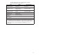
Appendix A Technical Specifications Ambient Conditions D Storage temperature: -40oC to 85oC -40oF to 185oF D Operating temperature (at the module): 0_C to 60_C 32_F to 140_F D Humidity: 5Ć90% nonĆcondensing Dimensions D Height: 9.25 inches (23.5 cm) D Width: 2.94 inches (7.5 cm) D Depth: 7.75 inches (19.1 cm including plugĆin connectors) D Weight: 4.5 lbsă(2.1 kg) Maximum Recommended Cable Length for Analog Signal Wiring D 50 feet (Belden 8761 or equivalent type) Maximum Power Dissipation D 4.
Operating range: 0Ć10 VDC Number of channels: 4 (singleĆended) Number of commons: 1 (shared among all 4 channels) Resolution: 12 bits binary NonĆlinearity: + 1 LSB maximum Accuracy: +.33% of full scale at 25oC maximum Thermal drift: + 50 ppm/degree C Type of converter: Successive approximation Speed of conversion: 13 usec Impedance: 180K Ohm + 0.
AĆC DĆCAĆC DĆC+ Vcc 12 PNT.
fafadfdfdasfdsfdsdsdfdsfdsfdsfsdfdsa afdfdsfdsfdfdsfdsfsadfda asfdfaddfdd
The following AutoMate program sequences can be used to interface to an AutoMate Processor that does not support the AIN block. Over a period of four scans, the program below inputs four channels from an Analog Rail module in Rail mode. Registers Used 0 Register that is configured to be updated at the end of scan.
If channel 2 was read in, put the data in register 42. 0.17 [ăă] 0.16 [Ă/Ă] Ă45.02 (ăă) EN MOVM EN LENGTH: 1 SRC: 0 SCR2: K0011ă1111ă1111ă1111 DEST: 42 If channel 3 was read in, put the data in register 43. 0.17 [ăă] 0.16 [Ăăă] Ă45.03 (ăă) EN MOVM EN LENGTH: 1 SRC: 0 SCR2: K0011ă1111ă1111ă1111 DEST: 43 At the End of Scan Select the channel to read in at end of scan. Ă44.00 [ăă] Ăă0.16 (ăă) Ă44.01 [ăă] Ăă0.17 (ăă) Increment counter 0, 1, 2, 3 and then back to 0.
fafadfdfdasfdsfdsdsdfdsfdsfdsfsdfdsa afdfdsfdsfdfdsfdsfsadfda asfdfaddfdd
For additional information 1 Allen-Bradley Drive Mayfield Heights, Ohio 44124 USA Tel: (800) 241-2886 or (440) 646-3599 http://www.reliance.com/automax Publication J-3688-2 - April 1993 Copyright © 2002 Rockwell Automation, Inc. All rights reserved. Printed in U.S.A.