
User Manual Owner manual

Rockwell Automation Publication 6181P-UM003A-EN-P - May 2014 29
Installation Chapter 2
•
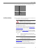
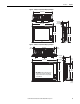
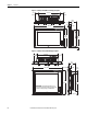
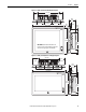
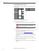
Display computers have mounting-assist clips on the top and bottom of the
bezel. When the computer is placed into a panel cutout, the mounting-assist
clips snap into place and hold the computer in position while you install the
mounting clips.
Certain restrictions apply when using mounting-assist clips. See Figure 15
for detail
s
.
Figure 15 - Acceptable and Unacceptable Mounting Positions for Using Assist Clips
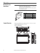
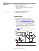
Panel Cutout Dimensions
A cutout template is shipped with each display computer model. 6181P and
6181X Integrated Display Industrial Computers Cutout Template, publication
6181P-DS002
, is included with standard display models (4:3 and 5:4 aspect
ratios). 6181P Integrated Display Industrial Computers Cutout Template,
publication 6181P-DS003
, is included with widescreen display models (16:9
aspect ratio).
The computers must be mounted to meet the panel cutout dimensions specified
below.
ATTENTION: The mounting-assist clips on display computers are no substitute
for the mounting clips. You must install the mounting clips for safety, NEMA, UL
Type, and IEC IP compliance.
Failure to follow these guidelines can result in personal injury or damage to the
panel components.
Model
Cutout Dimensions (H x W), approx
Standard Models Widescreen Models
1200P 254.0 x 324 mm (10.0 x 12.76 in.) —
1500P 285.6 x 386.6 mm (11.24 x 15.22 in.) 260.2 x 420 mm (10.24 x 16.54 in.)
1700P 329.5 x 424 mm (12.97 x 16.69 in.) —
1900P 363.5 x 449.6 mm (14.31 x 17.7 in.) 321 x 493 mm (12.64 x 19.41 in.)
AcceptableUnacceptable
≤60°
from Vertical
≤60°
from Vertical
0°