
User Manual Owner manual


Rockwell Automation Publication 6181P-UM003A-EN-P - May 2014 15
Features Chapter 1
Internal Components
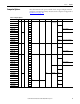
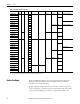
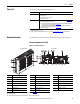
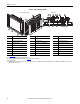
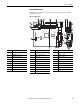
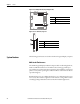
The illustrations in this section show the system board layouts for all non-display
and display computers.
Figure 3 - Motherboard
21
20
18
3
2
4
6
7
8
9
10
17
16
15
131211
1
22
23
24
25
262728
5
14
19
Item Component Item Component Item Component
1 Power connector 10 Clear UEFI button 20 DisplayPort connector
2 Mini-SATA cable connector, 2 11 Riser-card board connector 21 Microphone-in jack
3 eDP signal cable connector 12 Battery socket 22 PS/2 keyboard port
4 Panel cable connector 13 1 Gb LAN 2 port 23 Audio line-out jack
5 Power switch cable connector 14 1 Gb LAN 1 port 24 PS/2 mouse port
6 USB cable connector 15 DVI-I port 25 Audio line-in jack
7 ODD and HDD power cable connector 16 Rear USB 3.0 ports, 4 26 COM1 cable connector
8 System fan 1 connector 17 RS-232 serial port, (COM2) 27 COM2 cable connector
9 Internal USB 3.0 connector 18 CompactFlash Type II slot 28 DDR3 DIMM slot, 2
19 RS-232 serial port (COM1)