
User Manual

1–20 Introduction to the RAC6182
Publication 6182-UM002B-EN-P
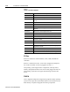
Table F
Layout of the Bezel EEPROM
Addresses (Hex) Purpose
0x00-0x01 16 bit CRC of the remainder of bezel EEPROM data
0x02-0x0F Reserved for future system use
0x10-0x11 Touch screen ID (0=4 wire res, 1=5 wire res, 0xffff =
none)
0x12-0x13 Magic cookie to tell if calibration data is valid
0x14-0x1F Reserved for future touch screen driver use
0x20-0x2F Touch screen calibration information
0x30-0x31
Keypad ID (0 = 56 key pad, 1 = 84 key pad, 0xffff = no
keypad)
0x32-0x3F Reserved for future keypad driver use
0x40-0x41 LCD panel ID (0 = 7” STN, 1 = 12” TFT, 0xffff = no LCD)
0x42 Minimum allowable contrast for this particular panel
0x43 Maximum allowable contrast for this particular panel
0x44
Default contrast for this particular panel if registry
contrast is invalid
0x45 Minimum allowable brightness for this particular panel
0x46 Maximum allowable brightness for this particular panel
0x47
Default brightness for this particular panel if registry
brightness is invalid
0x48-0x5F Reserved for future video driver use
0x60-0x7F Reserved for future operating system use
0x80-0xFF Application area. Will not be used by operating system
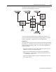
PCI Bus
PCI bus 0 contains the onboard Ethernet, video, USB, and PCMCIA
controllers.
PCI bus 1 contains the PCI slot. From a PCI configuration standpoint,
the virtual slot number of a device plugged in the slot is 1.
The operating system supports basic configuration, interrupt control,
memory management and IO access for PCI cards plugged into this slot.
The operating system does not support bus-mastering by the PCI slot
device.
PCMCIA
New or upgraded components of application programs and the operating
system can be copied from the PCMCIA memory card to Disk-On-Chip
flash memory to replace and upgrade the existing components.