6182 Industrial Computer Software Development Kit User Manual
Important User Information Solid state equipment has operational characteristics differing from those of electromechanical equipment. "Safety Guidelines for the Application, Installation, and Maintenance of Solid State Controls" (Publication SGI-1.1) describes some important differences between solid state equipment and hard-wired electromechanical devices.
Table of Contents Using this Manual Preface Who Should Use This Manual ...................................................P-1 Purpose of this Manual ..............................................................P-1 Contents of this Manual .............................................................P-1 Manual Conventions ..................................................................P-2 Allen-Bradley Support ...............................................................
toc-ii Table of Contents Appendix A Operating System Files .............................................................A-1 Memory Usage ..........................................................................A-2 Connecting an External Debug Monitor....................................
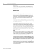
Preface Using this Manual Read this preface to familiarize yourself with the rest of the manual. The preface covers the following topics: who should use this manual the purpose of the manual contents of the manual conventions used in this manual Allen-Bradley support Who Should Use This Manual Use this manual if you are responsible for developing application software to run on the 6182 Windows CE Industrial Computer.
P–2 Using this Manual Manual Conventions The following conventions are used throughout this manual: Bulleted lists such as this one provide information, not procedural steps. Numbered lists provide sequential steps or hierarchical information.
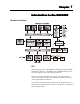
Chapter 1 Introduction to the RAC6182 Hardware Architecture CPU The system processor is a QED RM5231 embodying the popular MIPS 4300 RISC architecture. The RM5231 has a 225MHz clock speed, 64bit internal registers and a built in floating point unit. The system processor communicates directly with various memory devices, a V320 bus controller, and a super I/O controller by way of a 32-bit system address and data bus. The V320 bus controller manages system dynamic RAM for the 5231.
1–2 Introduction to the RAC6182 System Timers At least one (and in some cases, depending on the hardware revision level, more than one) programmable hardware timer is available at the application layer. Memory Devices Disk-On-Chip Flash ROM The Disk-On-Chip device (commonly called the “DOC”) is a flash ROM (32MB to 256MB, field upgradable) that emulates a disk device. The Disk-On-Chip device has two partitions or logical storage areas.
Introduction to the RAC6182 1–3 Retentive Memory (Battery Backed RAM) A 128 KB non-volatile memory provides application accessible storage for state information and data logging operations. A Lithium battery with a 10-year shelf life provides for long term data retention. It is recommended that applications using the retentive memory monitor battery voltage; this is easily done with system calls to the RAC6182’s hardware monitor.
1–4 Introduction to the RAC6182 Real Time Clock The super I/O chip provides a Real Time Clock which keeps the system date and time. Watch Dog The super I/O chip provides a watchdog timer that can be used to trigger a system reset. At system initialization, the watchdog is disabled. It can be enabled by an application. Once the watchdog is enabled, one or more applications must periodically “tag” (restart) it to prevent it from timing out. If the watchdog times out, a system reset (warm-boot) is initiated.
Introduction to the RAC6182 1–5 keypad handler can be replaced by a custom keypad handler to provide special key code mappings. Touch Screen An integral, resistive analog touch screen with a serial controller provides mouse-like operator input. The touch screen is a factory installed option associated with an integral display. PCI Subsystem The V320 chip provides a bridge between the 32-bit system address/data bus and the PCI bus. Several devices are attached to the PCI bus.
1–6 Introduction to the RAC6182 expansion and one for communications; one or two for memory expansion; one or two for communications. PCI Slot One half-length PCI slot provides an expansion capability for communication and I/O. The PCI slot can accommodate a large assortment of specialized and commercially available PCI add-in cards when suitable drivers are available. The device installed in the PCI slot will be device x on PCI bus 1.
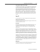
Introduction to the RAC6182 1–7 The operating system image that is loaded resides in the operating system partition of the Disk-On-Chip device. However, before loading the Disk-On-Chip boot image, the boot code checks for the presence of a PCMCIA memory device that is capable of supplying a boot image. The flow diagram that follows describes the boot sequence.
1–8 Introduction to the RAC6182 generator time to stabilize. Finally, system DRAM is tested. In the interest of reducing boot time, this test is limited to an address check; no attempt is made to identify bit errors at given addresses. Tests for Boot Devices When hardware testing has been completed, the boot code starts looking for PCMCIA devices capable of supplying a compressed operating system image. The boot code first checks for the presence of a PCMCIA ATA memory device.
Introduction to the RAC6182 1–9 “Warm Boot” After the registry merge, a “warm boot” is begun. Control passes to the operating system kernel, which can now use the registry image to initialize various subsystems. The file system drivers, the graphical subsystem drivers, serial, network, PS/2, USB, and other device drivers are loaded and initialized. The Windows CE Registry The Windows CE Registry contains application and system configuration data.
1–10 Introduction to the RAC6182 The operating system boot process is responsible for merging the default operating system Registry keys with the keys from the persistent Registry. If the same keys exist, preference is given to the persistent registry file. A few default keys are exceptions to this rule and are bypassed during the merge; e.g. the O/S version number is acquired from the O/S image.
Introduction to the RAC6182 1–11 During an uncontrolled shutdown (i.e. hard-power down), the system does not have enough time to flush the registry to persistent storage. Therefore, the registry must have been flushed by one of the means described above or else changes to the registry since the last flush will be lost. It is recommended that the controlled shutdown procedure be used for shutdown even if other registry flushing by applications is in place.
1–12 Introduction to the RAC6182 Table C RAM File System Directory Description \Temp Not used \My Documents Not used \Program Files Contains links (shortcuts) to certain system executables \Program Files \Communications Contains links (shortcuts) to certain system executables \Windows Contains system executables (*.exe), dynamic link libraries (*.dll), fonts (*.ttf), etc.
Introduction to the RAC6182 1–13 Input Device Handlers Touch Screen The RAC6182’s display can be equipped with a high resolution resistive touch screen. The Windows CE operating system incorporates a driver for the touch screen. A user interface is provided to enable touch screen configuration and calibration. Touch screen calibration values are stored in the registry. Keyboards The RAC6182 is designed to take key input from multiple sources.
1–14 Introduction to the RAC6182 Driver Publication 6182-UM002B-EN-P Description \windows\usbhid.dll USB Human Interface Device driver, loaded by DEVICE.EXE upon insertion of a USB Human Interface Device. Handles USB keyboard and mouse. Responsible for low-level USB related items and scan code to virtual key mappings for USB keyboard. Submits virtual key codes to kbdmouse.dll. \windows\keypad.dll RAC6182 specific keypad driver, loaded by DEVICE.EXE at startup.
Introduction to the RAC6182 1–15 The following figure schematizes the functional relations between the various drivers in the keyboard subsystem. As can be seen from the table and the accompanying schematic, the functions of the RAC6182 bezel keypad are supported by two separate software components: a keypad driver, and a keypad handler. Keypad Driver The keypad driver supports low level functions associated with standard keyboards (e.g.
1–16 Introduction to the RAC6182 Support for assignment of special functions to key operations by application programs. Support for a ‘single-key’ mode, in which keystrokes are processed one at a time. Following an initial key-down event, any other keydown or key-events will be ignored until the key-up event corresponding to the initial key-down event has been detected and processed.
Introduction to the RAC6182 1–17 perform translations of Virtual Key codes before the keypad driver passes these codes to the main keyboard driver for final processing. Thus, it functions as an intermediate processor between the keypad driver and the main keyboard driver. The keypad handler maintains its own key mapping and attribute tables separate from those maintained by the keypad driver.
1–18 Introduction to the RAC6182 Global key setting information is listed here by key and value. [HKEY_LOCAL_MACHINE\Drivers\BuiltIn\Keypad\Params\TypematicRepeat] “Enabled” REG_DWORD which is 1 for enabled, 0 for disabled “RepeatDelay” REG_DWORD of initial repeat delay in ms. “RepeatRate” REG_DWORD of subsequent repeat delay in ms.
Introduction to the RAC6182 1–19 The current contrast and brightness values are individual user preferences rather than traits of the panel, so are stored in registry rather than in the bezel EEPROM. However, if the registry contrast or brightness value is not present or not in the min/max range specified for the panel by the bezel EEPROM data, a default value is used from the bezel EEPROM.
1–20 Introduction to the RAC6182 Table F Layout of the Bezel EEPROM Addresses (Hex) Purpose 0x00-0x01 16 bit CRC of the remainder of bezel EEPROM data 0x02-0x0F Reserved for future system use 0x10-0x11 Touch screen ID (0=4 wire res, 1=5 wire res, 0xffff = none) 0x12-0x13 Magic cookie to tell if calibration data is valid 0x14-0x1F Reserved for future touch screen driver use 0x20-0x2F Touch screen calibration information 0x30-0x31 Keypad ID (0 = 56 key pad, 1 = 84 key pad, 0xffff = no keypad)
Introduction to the RAC6182 1–21 In the Windows Explorer, the PCMCIA Memory Card will show up as an icon named “\Storage Card2”. Application Run Time Environment Path The notion of a path to executable files is much the same as with any other Windows or DOS system. However, unlike other systems, which refer to an environment variable for path settings, Windows CE utilizes a registry entry. Thus, the path can be set only by editing the value of the registry key \HKLM\Loader\SystemPath.
1–22 Introduction to the RAC6182 completed startup, so dependencies should not be placed directly on explorer.exe. Consequently, the start menu, taskbar, etc. may still be drawing when oemstartup.exe is called. Although there is a \windows\startup folder in the file system, the placement of a shortcut in this folder in order to start the associated application automatically at system startup is not recommended.
Chapter 2 Developing CE Drivers and Applications for the RAC6182 General Considerations There are two general considerations for developing drivers and applications for the RAC6182: Distributing and installing applications Persistence considerations Application Distribution and Installation Application programs for the RAC6182 will consist of EXE and DLL files that will reside in the FAT partition of the Disk-On-Chip. They will be installed much like applications for Windows desktop operating systems.
2–2 Developing CE Drivers and Applications for the RAC6182 Installing the Application Once the user has obtained an installation script by one of these methods and the script resides on the user’s local desktop PC, he or she may use any of three methods to install the application on the RAC6182. Perform a remote installation by running the script on a PC host that is connected to the RAC6182 using Data Exchange.
Developing CE Drivers and Applications for the RAC6182 2–3 RAC6182 and all similar embedded devices since the Icons, the Start Menu, and application-provided Control Panel Applets must be recreated at startup. The solution is to place shortcuts in \Storage Card\Windows or in a directory under it.
2–4 Developing CE Drivers and Applications for the RAC6182 Windows CE Toolkit for Visual C++ 6.0 Platform SDK for H/PC – MIPSFP (from Windows CE Toolkit for Visual C++ 6.0) Or, Embedded Visual C++ 6.0 (from Microsoft Embedded Visual Tools 3.0) Platform SDK for H/PC – MIPSFP (from Microsoft Embedded Visual Tools 3.0) Note: The user of the Windows CE Toolkit for Visual C++ 6.0 should note that a special configuration step is necessary to work around a known limitation of that package.
Developing CE Drivers and Applications for the RAC6182 2–5 Setting Up the Host Machine for Basic Development First, Microsoft Windows CE Services (Active Sync) must be installed on the host system. This package provides utilities needed to download applications to the RAC6182, and to support a number of remote development tools. Windows CE Services is provided on CDROM with the RAC6182. The RAC6182 User’s Manual (Chapter 14) contains detailed information about installation.
2–6 Developing CE Drivers and Applications for the RAC6182 Next, the following Microsoft tools must be installed on the development platform in the order given: Microsoft Visual Basic 6.0 (from Visual Studio 6.0, Professional or Enterprise Edition) Windows CE Toolkit for Visual Basic 6.0 Platform SDK for H/PC - MIPSFP (from Windows CE Toolkit for Visual Basic 6.0) Or, Embedded Visual Basic (from Microsoft Embedded Visual Tools 3.0) Platform SDK for H/PC - MIPSFP (from Microsoft Embedded Visual Tools 3.
Developing CE Drivers and Applications for the RAC6182 2–7 The RAC6182 SDK is provided on CDROM. The CDROM contains two different development kits, one for the RAC6182 with CE V2.12, and one for the RAC6182 with CE V3.0. Either of these development kits may be installed separately. Most users will want to install the SDK for CE V3.0. Before installing the SDK for CE V3.0, it is recommended that any existing installation of the SDK for CE V2.12 be removed. All RAC6182s with CE V2.
2–8 Developing CE Drivers and Applications for the RAC6182 The RAC6182 SDK CDROM contains the following additional files: VBSDKReadme.txt - Information about the Visual Basic SDK VCSDKReadme.txt - Information about the Visual C++ SDK 6182api.txt - Visual Basic function definitions file Configuration After installing the SDK for CE V2.12, some special configuration is required. This applies only to the SDK for CE V2.12. The following steps are not required for the CE V3.0 SDK.
Developing CE Drivers and Applications for the RAC6182 2–9 No special configuration is necessary for Embedded Visual Basic.
Chapter 3 RAC6182 CE SDK Overview The RAC6182 SDK provides developers with access to an extensive set of functions that are specific to the RAC6182 hardware and constitute extensions of the standard Windows CE API. These functions, like the standard Windows CE functions, are implemented in the C language and can be called directly from C or C++ programs. Basic programs can also call these functions. However, Basic programs must declare the functions in the proper form before invoking them.
3–2 RAC6182 CE SDK On the other hand, users of this IDE who wish to write in standard C should keep in mind that this default situation will require all standard C modules to be conditionally bracketed in the same way that the headers in the SDK are bracketed.
Chapter 4 RAC6182-Specific Extensions to the CE API Functions for Digital Output Control The functions described in this section provide application level access to all digital outputs on the RAC6182 via a common interface. The digital outputs include four diagnostic outputs on pins A, B, C and D of header J10 on the system board, and a relay output, with contacts terminated at connector J16, which accessible from the rear of the RAC6182.
4–2 RAC6182-Specific Extensions to the CE API Macro Digital Output MASK_DIAG_PIN_D J10, pin D (no external access) MASK_RELAY_PIN J16 (Relay, contacts NC) Return Value TRUE if read operation was successful, else FALSE. Portability This function is specific to the RAC6182 hardware. Example #include #include
RAC6182-Specific Extensions to the CE API 4–3 Note that the relay contacts are normally closed (i.e., closed when the relay is not energized). Thus, when the relay output is set to 1 or TRUE, the contacts will be open and vice versa. The following macros can be used (separately or bitwise ORed together) to evaluate ucMask.
4–4 RAC6182-Specific Extensions to the CE API do_SetBits This function sets digital outputs. It is prototyped in DiagnosticOutputAPI.h. Syntax #include #include BOOL do_SetBits(UCHAR ucMask) Remarks This function sets any output whose bit is 1 in ucMask to logic TRUE. For the relay output, logic TRUE is equivalent to closed; for TTL outputs, it is equivalent to TTL high level. All pins whose bit is 0 in ucMask are left unchanged.
RAC6182-Specific Extensions to the CE API 4–5 do_ClearBits This function clears digital outputs. It is prototyped in DiagnosticOutputAPI.h. Syntax #include #include BOOL do_ClearBits(UCHAR ucMask) Remarks This function clears any output whose corresponding bit in ucMask is 1 to a logic FALSE. For the relay output, FALSE is equivalent to open; for TTL outputs, it is equivalent to a low level. All outputs whose bits in ucMask are 0 are left unchanged.
4–6 RAC6182-Specific Extensions to the CE API do_ToggleBits This function toggles digital outputs. It is prototyped in DiagnosticOutputAPI.h. Syntax #include #include BOOL do_ToggleBits(UCHAR ucMask) Remarks Outputs corresponding to bits in ucMask that are set to 1 are toggled. For any output whose bit is 1 in ucMask, if its previous output was TRUE (closed or high) it will be set FALSE (open or low) and viceversa. All pins whose bit is 0 in ucMask are left unchanged.
RAC6182-Specific Extensions to the CE API Functions to Read from and Write to the Bezel EEPROM 4–7 The bezel EEPROM provides a total of 256 bytes of non-volatile storage. The first 128 bytes (at offsets 0x00 through 0x7f) are reserved for use by the CE operating system and built-in device drivers (specifically, those drivers that handle devices attached to the bezel, namely the keypad, touch screen and display). The remaining 128 bytes (at offsets 0x80 through 0xff) are reserved for future use.
4–8 RAC6182-Specific Extensions to the CE API Return Value The possible return values are represented by the following macros, defined in bezeleeprom.h: Macro Description BEZEL_EEPROM_OK EEPROM present, arguments valid, function completed successfully. BEZEL_EEPROM_ DEVICE_NOT_ PRESENT No EEPROM detected – either bezel not present or EEPROM on it not functioning. BEZEL_EEPROM_ INVALID_ PARAMETER Bad parameter passed to function, for example a NULL pointer or an address out of range.
RAC6182-Specific Extensions to the CE API 4–9 Remarks Sets access mode or recalculates CRC, depending on dwParameter and the value of *pdwData. dwParameter may be evaluated using one of the following macros: Macro BEZEL_EEPROM_ PARAMETER_USE_ CRC Description Set CRC mode. If the value of *pdwData is 1, CRC mode is enabled. If the value of *pdwData is 0, CRC mode is disabled.
4–10 RAC6182-Specific Extensions to the CE API be_ReadBezelEEPROM This function reads bezel EEPROM. It is prototyped in bezeleeprom.h. Syntax #include #include DWORD be_ReadBezelEEPROM(DWORD dwAdress, DWORD dwLength, UCHAR *pucData) Remarks Reads dwLength bytes starting at offset dwAddress in the EEPROM into a caller allocated buffer beginning at pucData. All reads are implicitly mutexed.
RAC6182-Specific Extensions to the CE API 4–11 be_WriteBezelEEPROM This function (prototyped in bezeleeprom.h) is intended for use by operating system developers only. Rockwell Automation recommends against and does not support use of this function in application programs or user implemented device drivers. ATTENTION: Improper use of this function could result in disruption of critical system level data.
4–12 RAC6182-Specific Extensions to the CE API started, but if the value of dwTimeout is out of range for the hardware implementation of the timer, the timeout setting of the watchdog is left unmodified and WATCHDOG_TIMEOUT_FAILED is returned. Values of dwTimeout over 5000 should never be used, because they cannot be guaranteed to be within range for a given hardware implementation. At the time of writing, the maximum timeout period supported by the hardware is 3478 msec.
RAC6182-Specific Extensions to the CE API 4–13 A custom handler might implement these functions in a different way. However, these functions are subject to redefinition. Accordingly, Rockwell Automation currently recommends against and does not support customer implementations of these functions. KhInitialize Rockwell Automation currently recommends against and does not support customer implementation of this function.
4–14 RAC6182-Specific Extensions to the CE API Streams Interface for Keypad Driver Control The keypad related macros and special IOCTLs defined in KeypadAPI.h are intended for use by system developers only. Rockwell recommends against and does not support their use by customers. Standard I/O streams functions called with these special constants as arguments provide a means for the calling software module to control the system keypad driver (keypad.dll).
RAC6182-Specific Extensions to the CE API 4–15 NLedGetDeviceInfo This function gets the LED Status Information. Syntax #include #include BOOL NLedGetDeviceInfo(UINT nInfoId, void *pOutput) Remarks Use this function to request information about the system LEDs. Information that is accessible with this function includes the number of LEDs installed, the capabilities of each installed LED, and the current settings for each installed LED.
4–16 RAC6182-Specific Extensions to the CE API Macro NLED_SUPPORTS_ INFO_ID Description Use to request capability information about any one of the LEDs in the system. pOutput should point to a caller allocated structure defined (in nleddrv.
RAC6182-Specific Extensions to the CE API 4–17 Portability The arguments to this function are specific to the RAC6182 hardware. NledSetDevice This function sets the LEDs. Syntax #include #include
4–18 RAC6182-Specific Extensions to the CE API Remarks Use this function to set the operating states of the system LEDs. Note: Before calling this function, it is a good idea to issue a calls to the NLedGetDeviceInfo function to verify the presence of the LED of interest and to get its capabilities. As of this writing, RAC6182s with integrated LCDs are equipped with three front panel LEDs which have only “on” and “off” capabilities.
RAC6182-Specific Extensions to the CE API 4–19 Microsoft, so this document will focus just on RAC6182 specific features or limitations and recommended usage in application level code or user mode device drivers. ceddk.h and ceddk.lib must be used for compilation and linking in addition to the default libraries.
4–20 RAC6182-Specific Extensions to the CE API HalTranslateBusAddress This function translates the PCI Bus Address. Syntax #include #include
RAC6182-Specific Extensions to the CE API 4–21 HalGetBusDataByOffset This function gets the PCI Bus Data by offset. Syntax #include #include ULONG HalGetBusDataByOffset( BUS_DATA_TYPE BusDataType, ULONG BusNumber, ULONG SlotNumber, PVOID Buffer, ULONG Offset, ULONG Length ) Remarks HalGetBusDataByOffset() retrieves PCI configuration space information, such as addresses and interrupt information, for a PCI device.
4–22 RAC6182-Specific Extensions to the CE API HalSetBusDataByOffset This function sets the PCI Bus Data by offset. Syntax #include #include ULONG HalSetBusDataByOffset( BUS_DATA_TYPE BusDataType, ULONG BusNumber, ULONG SlotNumber, PVOID Buffer, ULONG Offset, ULONG Length ) Remarks HalSetBusDataByOffset() sets PCI configuration space information. This function should be used only to set device-specific configuration information.
RAC6182-Specific Extensions to the CE API 4–23 MmMapIoSpace This function maps the PCI IO space. Syntax #include #include PVOID MmMapIoSpace( PHYSICAL_ADDRESS PhysicalAddress, ULONG NumberOfBytes, BOOLEAN CacheEnable ) Remarks MmMapIoSpace() maps a physical address range into a virtual address range usable by an application. This function should be used on PCI memory or IO range information obtained with HalGetBusDataByOffset() and translated with HalTranslateBusAddress().
4–24 RAC6182-Specific Extensions to the CE API (offset 0x0C) using HalGetBusDataByOffset(). The PCI slot interrupt is disabled until this function is called. Portability The argument to this function is specific to the RAC6182 hardware. InterruptDisable This function disables the PCI interrupt. Syntax #include #include VOID InterruptDisable ( DWORD idInt ) Remarks InterruptDisable() disables the virtual interrupt.
RAC6182-Specific Extensions to the CE API 4–25 Portability The argument to this function is specific to the RAC6182 hardware. Sample Code for a Simple PCI Slot Device This code assumes a simple device with one memory address space size 4K configured at PCI configuration offset 0x10 and one IO address space size 16K configured at PCI configuration offset 0x14. It has a power management register at offset 0x40 that must be set to bring the device out of power down mode.
4–26 RAC6182-Specific Extensions to the CE API NKDbgPrintfW(TEXT(“failed to set device specific PCI config value\n”)); return(-1); } // get virtual interrupt # interrupt=PCIConfig.u.type0.
RAC6182-Specific Extensions to the CE API 4–27 return(0); } NKDbgPrintfW(TEXT(“card said mem %08x IO %08x\n”), *(ULONG *)MemSpace, *(ULONG *)IOSpace); // done processing interrupt, reenable and wait again InterruptDone(interrupt); } else { } } Functions for OS Update NKDbgPrintfW(TEXT(“waitforsingleobject failed\n”)); return(-1); } The functions prototyped in osupdateapi.h are intended for use by system developers only.
4–28 RAC6182-Specific Extensions to the CE API FlushRegistry This function is the Flush Registry. It is prototyped in regflush.h. Syntax #include #include BOOL RegistryFlush(void) Remarks This function is defined as a macro in regflush.h. This function commands the operating system to flush the entire registry to the persistent registry storage. The procedure that occurs when this API is invoked is as follows: 1. The entire registry information is collected from Windows CE. 2.
RAC6182-Specific Extensions to the CE API 4–29 the overall size and the nature of the content may also affect compressibility. Time involved to flush the registry varies based on size of the registry, and can also vary based on state of the Disk-On-Chip (e.g. if flash sectors need erased and written this takes significantly longer than just writing to previously erased flash sectors). For the registry in the base operating system time to flush has been seen to vary between 100 to 500 ms.
4–30 RAC6182-Specific Extensions to the CE API dwStorePages the number of 4KB pages to be allocated to the system. Important: Windows CE V2.12 could exhibit problems if more than 32MB of DRAM is allocated to the system. Return Value TRUE if successful, otherwise FALSE. Portability This function is specific to the RAC6182 hardware. Functions to Get/Set Misc Parameters The functions described here may be called by an application program to get or set the values of certain system parameters.
RAC6182-Specific Extensions to the CE API Parameter Macro Identifier Get or Set Type 4–31 Size (Bytes) Debug output on COM2 RM_PARAMETER_ENABLE_SERIAL_DEBUG_ON_BOOT Both BOOL 4 LCD Brightness RM_PARAMETER_LCD_BRIGHTNESS Both DWORD 4 LCD Contrast RM_PARAMETER_LCD_CONTRAST Both DWORD 4 MAC Addr of on board Ethernet RM_PARAMETER_ONBOARD_ETHERNET_MAC_ADDRESS Get UCHAR 6 Cursor Status RM_PARAMETER_CURSOR_ENABLED Both BOOL 4 Debug output on COM2 RM_PARAMETER_ENABLE_SERIAL_DEBUG Bo
4–32 RAC6182-Specific Extensions to the CE API RM_PARAMETER_LCD_CONTRAST RM_PARAMETER_ONBOARD_ETHERNET_MAC_ADDRESS RM_PARAMETER_CURSOR_ENABLED RM_PARAMETER_ENABLE_SERIAL_DEBUG RM_PARAMETER_PHYSICAL_ADDRESS (CE V3.0 only) dwSize is a pointer to a caller allocated DWORD whose value will represent the number of bytes at pvData. pvData is a pointer to a caller allocated buffer which will contain information related to the current settings for the selected parameter.
RAC6182-Specific Extensions to the CE API 4–33 RM_PARAMETER_ENABLE_SERIAL_DEBUG_ON_BOOT RM_PARAMETER_LCD_BRIGHTNESS RM_PARAMETER_LCD_CONTRAST RM_PARAMETER_CURSOR_ENABLED RM_PARAMETER_ENABLE_SERIAL_DEBUG RM_PARAMETER_PHYSICAL_ADDRESS (CE V3.0 only) dwSize is a pointer to a caller allocated DWORD. *dwSize should be evaluated with sizeof() or with the size in bytes of the parameter type as indicated in the table at the beginning of this section.
4–34 RAC6182-Specific Extensions to the CE API UserTimerGetNumberOfTimers This function gets the number of available timers. It is prototyped in usertimers.h. Syntax #include #include DWORD UserTimerGetNumberOfTimers(void) Remarks Returns total number of application accessible timers on the system. Return Value Total number of application accessible timers available. Portability This function is specific to the RAC6182 hardware.
RAC6182-Specific Extensions to the CE API 4–35 Remarks This function is used to claim or release exclusive access to a specific timer. A timer must be claimed before any function taking a TimerNumber as a parameter can be used. A timer must be released to allow any other application to claim and use the timer. Parameter Description TimerNumber TimerNumber is 0 based (i.e. if 2 timers are present on the system, they are timer #0 and timer #1).
4–36 RAC6182-Specific Extensions to the CE API Applications must check the *Frequency returned and use it in their counter calculations. Note: As of this writing, RAC6182 user timers operate at a fixed frequency of 75MHz. Thus, attempts to adjust the timers to frequencies other than 75MHz will not be effective. However, the timers’ frequencies may become adjustable in future releases of the RAC6182, and no guarantee can be made that the timers will always have a fundamental frequency of 75MHz.
RAC6182-Specific Extensions to the CE API 4–37 UserTimerSet This function sets the count of user timer and start timing. It is prototyped in usertimers.h. Syntax #include #include DWORD UserTimerSet(DWORD TimerNumber,DWORD Count) Remarks Sets the timer to a given countdown value and starts the timer. The frequency of the count is the last frequency returned from UserTimerRequestFrequency. The countdown stops at 0 and the timer is triggered.
4–38 RAC6182-Specific Extensions to the CE API UserTimerStop This function stops the user timer. It is prototyped in usertimers.h. Syntax #include #include DWORD UserTimerStop(DWORD TimerNumber) Remarks Aborts any currently active countdown in the timer specified by TimerNumber. TimerNumber must refer to a previously claimed timer. Return Value Possible return values are represented by macros defined in usertimers.h.
RAC6182-Specific Extensions to the CE API Parameter 4–39 Description TimerNumber Number of a previously claimed timer. Count Pointer to a DWORD allocated by the caller in which the current count will be stored. Return Value Possible return values are represented by macros defined in usertimers.
4–40 RAC6182-Specific Extensions to the CE API Return Value Possible return values are represented by macros defined in usertimers.h: USER_TIMER_OK - Successfully claimed or released timer USER_TIMER_INVALID_TIMER - Timer number not present on system USER_TIMER_NOT_CLAIMED - Another application already has claimed the timer so this application could not claim it USER_TIMER_INVALID_PARAMETER - Invalid value Portability This function is specific to the RAC6182 hardware.
RAC6182-Specific Extensions to the CE API 4–41 The functions exported by the HardwareMonitor driver are listed below. hm_GetMonitorLevel This function gets the value of monitored parameter. It is prototyped in HardwareMonitorAPI.h. Syntax #include #include BOOL hm_GetMonitorLevel (DWORD dwMonitorID, double *plfMonitorLevel) Remarks This function queries the hardware monitor for the value of the parameter specified with dwMonitorID.
4–42 RAC6182-Specific Extensions to the CE API hm_GetMonitorWarningLevels This function gets warning levels for monitored parameter. It is prototyped in HardwareMonitorAPI.h. Syntax #include #include BOOL hm_GetMonitorWarningLevels (DWORD dwMonitorID, double *plfUpperWarningLevel, double *plfLowerWarningLevel) Remarks This function queries the current warning levels defined for the parameter specified with dwMonitorID.
RAC6182-Specific Extensions to the CE API 4–43 Parameter Description plfLowerWarningLevel Pointer to an application-allocated double-precision floating point where the current lower limit value will be written. The value represents volts or degrees Celsius, depending on the specified parameter. MONITOR_WARNING_LEVEL_UNDEFINED, a macro defined in HardwareMonitorAPI.
4–44 RAC6182-Specific Extensions to the CE API ATTENTION: When power fail lower warning level is set, and the 12V supply subsequently drops below that level, the system will enter a warning state, but it will also begin an irreversible shut down. Care should be taken not to set regular 12-Volt low warning level lower than the power fail level; otherwise, it will not be possible to detect a warning in case the 12V drops below its lower level.
RAC6182-Specific Extensions to the CE API 4–45 Portability This function is specific to the RAC6182 hardware. See Also hm_GetMonitorWarningLevels hm_RegisterMonitorWarningEvent This function registers to receive a warning of a parameter out-of-limit. It is prototyped in HardwareMonitorAPI.h. Syntax #include #include
4–46 RAC6182-Specific Extensions to the CE API The phEventHandle returned by this function is a standard Win32 autoreset event handle. However, an application should NOT close the handle using the handle using the Win32 CloseHandle function. Instead the application should close the handle and unregister the event using the hm_UnregisterMonitorWarningEvent function.
RAC6182-Specific Extensions to the CE API 4–47 Remarks This function unregisters and frees a warning state notification event that had previously been created using hm_RegisterMonitorWarningEvent. This function will automatically free hEventHandle, so the application should not attempt to free it with CloseHandle. Parameter hEventHandle Description Handle of the previously registered warning event that is now being unregistered and freed.
4–48 RAC6182-Specific Extensions to the CE API Parameter pdwMonitorID Description Pointer to an application-allocated DWORD that will receive a bitmask combination of all monitor sources currently in the warning state. The following macros defined in HardwareMonitorAPI.h can be used to test for specific parameters: MONITOR_ID_SUPPLY_3V MONITOR_ID_SUPPLY_5V MONITOR_ID_SUPPLY_12V MONITOR_ID_SUPPLY_BATTERY MONITOR_ID_TEMPERATURE_BOARD Return Value Returns TRUE if the function succeeds.
RAC6182-Specific Extensions to the CE API 4–49 hm_GetBootReason This function gets the reason for last boot. It is prototyped in HardwareMonitorAPI.h. Syntax #include #include DWORD hm_GetBootReason (void) Remarks This function returns a DWORD representing the reason the board was last booted. Magic cookies and intelligent selection of default cases are used to distinguish as many scenarios as possible.
4–50 RAC6182-Specific Extensions to the CE API Functions for Accessing Retentive Memory The RAC6182 software includes a Retentive Memory driver that can be called by applications to read and write to the RAC6182’s battery-backed RAM. The driver is implemented as a dynamic link library (). Retentive Memory driver functions available to applications include functions to lock and unlock the battery-backed RAM. When an application holds a lock on this RAM, no other application can read or write data.
RAC6182-Specific Extensions to the CE API 4–51 RetMemUnlock This function unlocks retentive memory. It is prototyped in RetentiveMemAPI.h. Syntax #include #include BOOL RetMemUnlock (void) Remarks The application should always call this function to release a lock on retentive memory before exiting. Return Value Returns TRUE if the lock is released. Returns FALSE on failure. Portability This function is specific to the RAC6182 hardware.
4–52 RAC6182-Specific Extensions to the CE API Parameter Description dwOffset Starting offset in RAM at which data will be written. Offset 0 is the first byte of RAM. dwLength Number of bytes to be written. pbtBuffer Pointer to a buffer containing data to be written to the RAM. Return Value Returns the total number of bytes actually written Portability This function is specific to the RAC6182 hardware. See Also RetMemRead RetMemRead This function reads retentive memory.
RAC6182-Specific Extensions to the CE API 4–53 Return Value Returns the number of bytes actually read. Portability This function is specific to the RAC6182 hardware. See Also RetMemWrite RetMemVerifyMemory This function verifies retentive memory. It is prototyped in RetentiveMemAPI.h. Syntax #include #include BOOL RetMemVerifyMemory (void) Remarks This function calculates the checksum of retentive memory and compares it to the master checksum.
4–54 RAC6182-Specific Extensions to the CE API RetMemCalculateChecksum This function calculates retentive memory checksum. It is prototyped in RetentiveMemAPI.h. Syntax #include #include BOOL RetMemCalculateChecksum (void) Remarks This function recalculates the checksum of retentive memory and writes it as the master checksum.
RAC6182-Specific Extensions to the CE API Streams Interface for Serial Ports 4–55 Applications can utilize the RAC6182 platform's serial ports via the standard WIN32 API's "File I/O" interface. A complete description of the File I/O interface is outside the scope of this document. Users are referred to the Microsoft Win32 SDK documentation for additional information. However, some of the arguments needed by the File I/O functions for serial port control are specific to the RAC6182.
4–56 RAC6182-Specific Extensions to the CE API Macro IOCTL_SERIAL_SET _PORT_MODE Description Sets the electrical interface for the specified serial port. Note that only COM1 supports switching electrical interfaces. lpInBuffer should point to a caller allocated WORD containing the code for the desired electrical interface. The possible codes are represented by the following macros defined in othersdk.h: SERIAL_MODE_RS232 SERIAL_MODE_RS485 SERIAL_MODE_RS422 nInBufferSize should be sizeof(WORD).
RAC6182-Specific Extensions to the CE API Macro IOCTL_SERIAL_GET _CABLE_STATUS 4–57 Description Do not use. Not supported on RAC6182. Portability The arguments to this function are specific to the RAC6182 hardware Application Interface to Output Debug Messages The RAC6182 provides support for an external debug monitor connected at the second serial port (COM2).
4–58 RAC6182-Specific Extensions to the CE API NKDbgPrintfW This function generates output to an external debug monitor. It is prototyped in dbgapi.h. Syntax #include #include void NKDbgPrintfW(LPWSTR lpszFmt, …) Remarks This is a var-args function similar to any of the printf() family, which takes a Unicode formatting string and zero or more other arguments. dbgapi.h defines macros RETAILMSG() and DEBUGMSG() which may be useful in setting up conditional debug outputs.
Appendix Appendix A Operating System Files Table J Operating System Files System Executables in Windows Function async.asy (ActiveSync) cmd.exe control.exe ctlpnl.exe Control Panel explorer.exe (Windows Explorer) Windows Explorer flashavr.exe format.exe iesample.exe (Internet Explorer) LocalOSUpdate.exe osmonitor.exe pegterm.exe (Terminal) ping.exe rapisvr.exe regflush.exe Saves RAM based registry to persistent storage remnet.exe (Remote Networking) repllog.exe (PC Link) rnaapp.exe wplayer.
A–2 Appendix A Function System Executables in Windows system icons cplmain.cpl Memory Usage Table K RAM Usage Component Memory Usage RAM FS space - Core OS components (kernel, networking, drivers) 4.0 MB RAM FS space - Windows desktop (commctrl, explorer, ctl panel, fonts) 3.0 MB RAM FS space – Internet explorer (browser object, HTML, javascript) 5.
Appendix A Connecting an External Debug Monitor A–3 The RAC6182 provides support for an external debug monitor connected at the second serial port. A debug monitor can be very useful for Windows CE operating system developers, since it can capture debug messages emitted by the operating system by way of a serial port, even before all Windows CE services, including display services, are operational.
Index B Bezel ID EEPROM, 1-18 C Central processing unit (CPU), 1-1 D Debug messages, 4-60 F Files C/C++ Development Kit, 3-2 local file systems, 1-11 Windows CE Registry, 1-9 Functions bezel EEPROM be_GetBezelEEPROMParameter, 4-7 be_ReadBezelEEPROMParameter, 4-10 be_SetBezelEEPROMParameter, 4-8 be_WriteBezelEEPROMParameter, 4-11 custom keypad handlers KhDeinitialize, 4-13 KhGetGlobalKeySettings, 4-13 KhGetKeyAttributeTable, 4-13 KhInitialize, 4-13 KhSetGlobalKeySettings, 4-13 KhTranslateVKey, 4-14 debug me
I–2 Index UserTimerClaim, 4-35 UserTimerGetNumberOfTimers, 4-35 UserTimerGetValue, 4-40 UserTimerGeWaitEvent, 4-41 UserTimerRequestFrequency, 4-36 UserTimerSet, 4-39 UserTimerStop, 4-40 watchdog timer Watchdog_Tag, 4-11 H Hardware architecture, 1-1 CPU, 1-1 memory devices battery backed RAM, 1-3 boot ROM, 1-2 Disk-on-Chip, 1-2 DRAM, 1-2 PCI subsystem, 1-5 super I/O, 1-3 host system setting up Basic development, 2-5 C/C++ development, 2-3 I Input device handlers, 1-13 Installation development system, 2-3 d
Index software archicture, 1-6 bezel ID EEPROM, 1-18 boot sequence, 1-6 development system, 2-3 distribution, 2-1 input device handlers, 1-13 installation, 2-2 local file systems, 1-11 operating system, 1-6 PCI bus, 1-20 persistence considerations, 2-2 registry, 1-9 runtime environment, 1-21 system shutdown, 1-22 upgrades, 2-2 Registry, 1-9 Runtime environment, 1-21 S SDK configuration, 2-8 debug messages, 4-60 files, 3-2 functions be_GetBezelEEPROMParameter, 4-7 be_ReadBezelEEPROMParameter, 4-10 be_SetBez
I–4 Index Software bezel ID EEPROM, 1-18 boot sequence, 1-6 input device handlers, 1-13 local file systems, 1-11 PCI bus, 1-20 runtime environment, 1-21 system shutdown, 1-22 Windows CE OS, 1-6 Windows CE Registry, 1-9 Publication 6182-UM002B-EN-P
IBM is a registered trademark of International Business Machines Corporation. VGA is a trademark of International Business Machines Corporation. PC AT is a trademark of International Business Machines Corporation. Microsoft is a registered trademark of Microsoft Corporation. Microsoft Windows is a trademark of Microsoft Corporation.